System and method for determining the beam center location of an antenna

a beam center and antenna technology, applied in the direction of antennas, instruments, antenna radiation diagrams, etc., can solve the problems of inaccurate determination of the beam center, adverse effects of commands provided to the antenna in order to alter the pointing direction, etc., and achieve the effect of accurately determining the beam center of the antenna

Active Publication Date: 2010-11-30
THE BOEING CO
View PDF13 Cites 5 Cited by
  • Summary
  • Abstract
  • Description
  • Claims
  • Application Information

AI Technical Summary

Benefits of technology

[0006]Various embodiments of the present invention are therefore provided for determining the beam center of an antenna. In this regard, embodiments of a system and method of the present invention permit the beam center of the antenna to be determined more accurately following deployment of the antenna by avoiding perturbations that may otherwise be introduced by the earth's atmosphere through which the antenna beam must travel. By more accurately determining the beam center of the antenna, the antenna may be more precisely positioned in order to align the actual beam center with the desired beam center.

Problems solved by technology

Since the earth's atmosphere is a thermally unstable dispersive media, the beam emitted by the antenna and, in turn, the antenna footprint on the ground may be altered by the atmosphere, thereby resulting in inaccuracies in the determination of the beam center.
As such, the commands provided to the antenna in order to alter its pointing direction may be adversely affected with the beam center of the antenna still being offset from its desired position.

Method used


Image

  • System and method for determining the beam center location of an antenna
  • System and method for determining the beam center location of an antenna
  • System and method for determining the beam center location of an antenna

Examples


Embodiment Construction

[0016]The present inventions now will be described more fully hereinafter with reference to the accompanying drawings, in which some, but not all embodiments of the inventions are shown. Indeed, these inventions may be embodied in many different forms and should not be construed as limited to the embodiments set forth herein; rather, these embodiments are provided so that this disclosure will satisfy applicable legal requirements. Like numbers refer to like elements throughout.

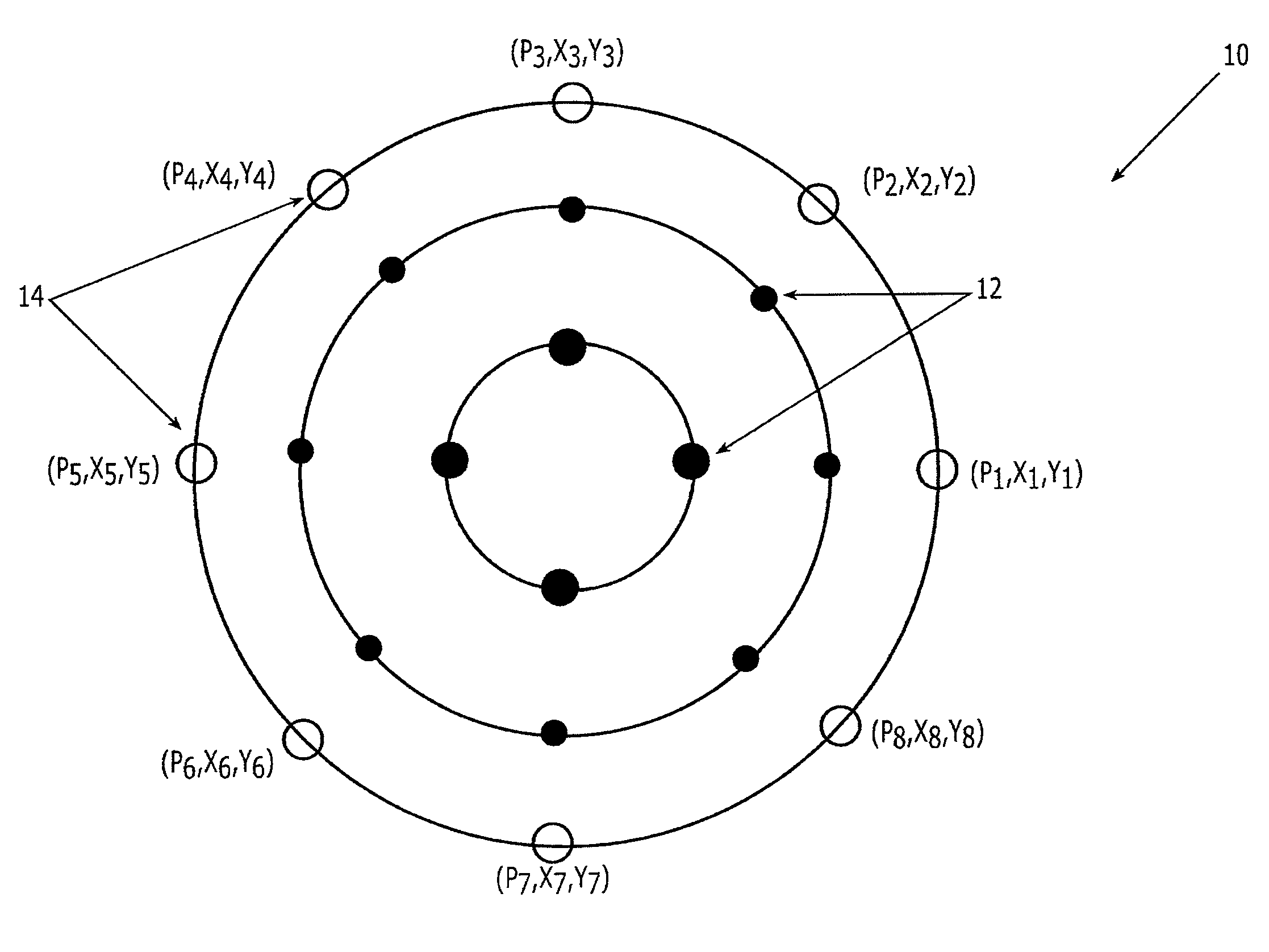
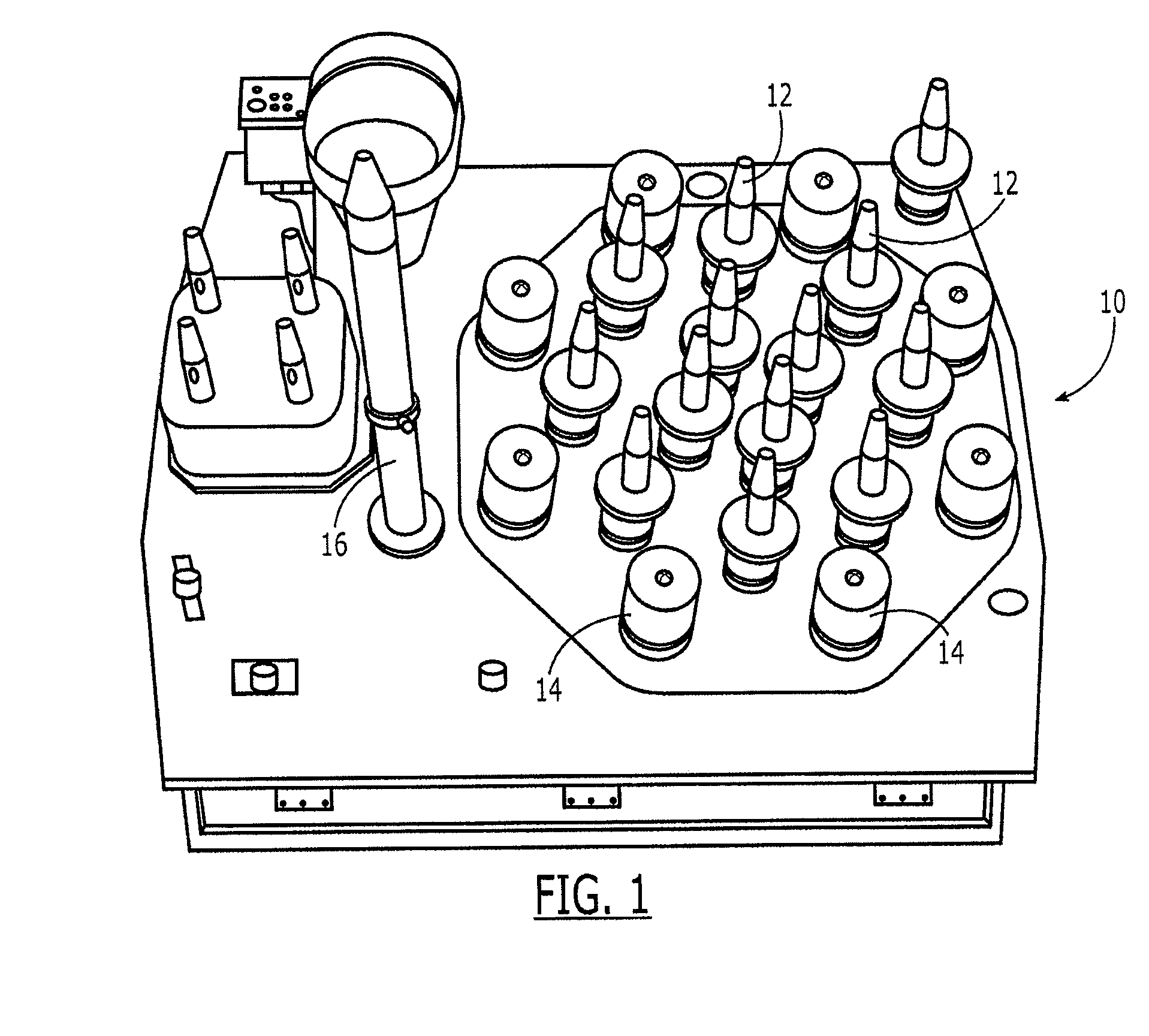
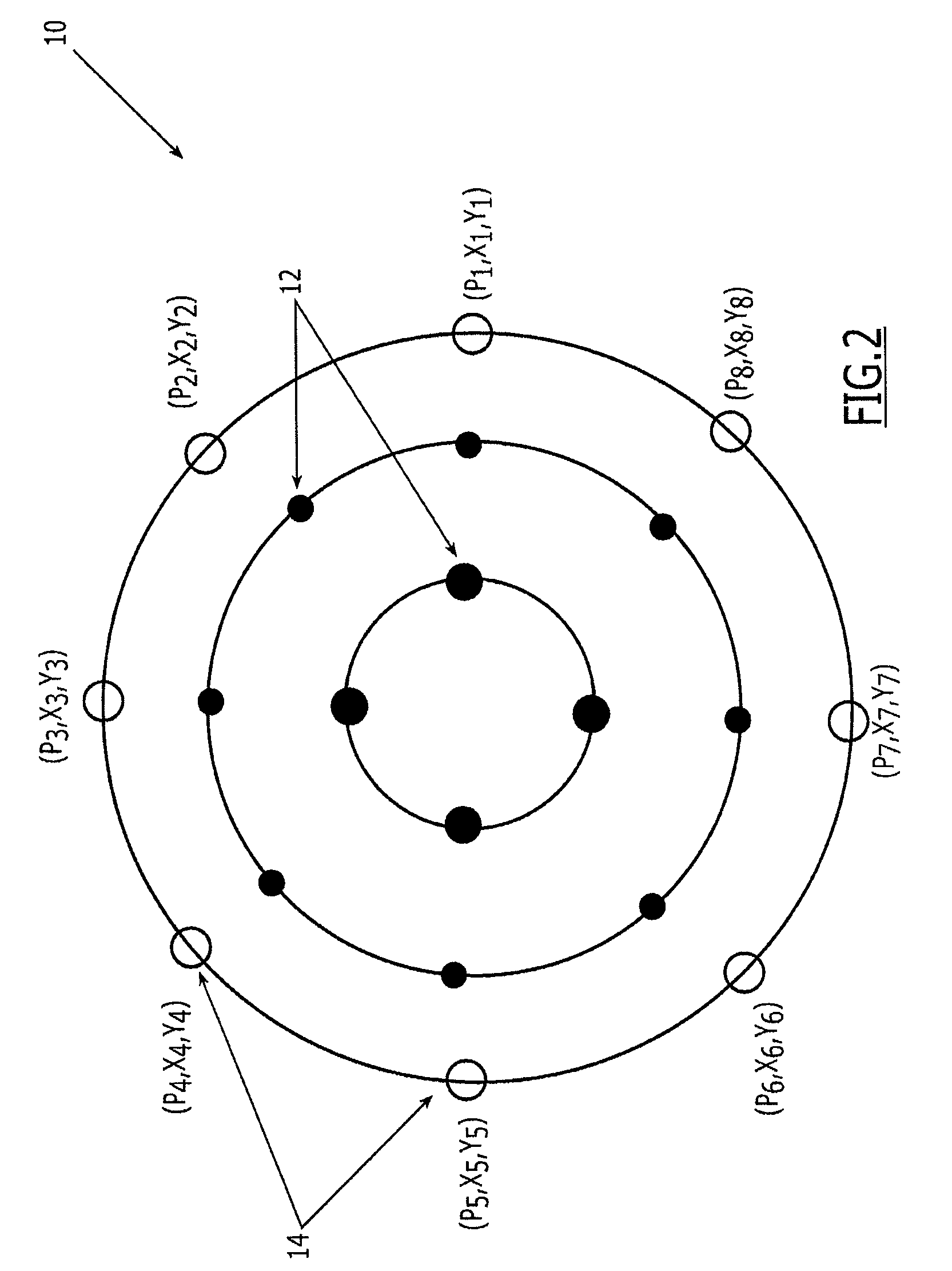
[0017]Referring now to FIG. 1, a Global Positioning System (GPS) antenna 10 is depicted. The GPS antenna includes a plurality of L-band antenna elements 12 disposed in a central or interior portion of the antenna for transmitting signals having frequencies in the L-band. The GPS antenna also includes a plurality of integrated transfer systems (ITS) antenna elements 14 that are generally positioned about and, therefore, surround the L-band elements. The ITS antenna elements may be used for crosslink purposes, s...


PUM


Abstract

A system and method for determining the beam center location of an antenna, such as a global positioning system (GPS) antenna, are provided. A system for determining the beam center of an antenna may include a plurality of radio frequency (RF) probes, such as Integrated Transfer System (ITS) antenna elements, located at respective predefined positions surrounding the geometrical center of the antenna. The system may also include at least one detector configured to provide a measure of the RF power detected by each respective RF probe. The system may also include a processor configured to determine the beam center of the antenna based upon the predefined position of each RF probe and the measure of the RF power detected by each respective RF probe. A corresponding method is also provided.

Description

FIELD OF THE INVENTION[0001]Embodiments of the present invention are generally directed to methods and systems for evaluating an antenna and, more particularly, to methods and systems for determining the beam center location of an antenna.BACKGROUND OF THE INVENTION[0002]An antenna or an antenna array (hereinafter collectively referenced as an “antenna”) shapes (by-design) radiated electromagnetic energy in specific patterns called beams. As such, the location of the center of the beam of an antenna also defines its pointing direction. For navigation satellites, it is useful to be able to point the beam of the navigation payload antenna to a specific location with increased precision as a jamming countermeasure, while for communications satellites, knowledge of the beam center permits communications to be conducted more efficiently. For example, more accurate pointing of the beam center of an antenna can facilitate communications at a lower power level or with improved throughput in...

Claims


Application Information

Patent Timeline
Patent Type & Authority Patents(United States)
IPC IPC(8): H01Q3/00G01S5/04
CPCG01R29/10
Inventor BENAVIDES, ARMANDO
Owner THE BOEING CO
Why Eureka
Try Eureka