Lawn mower cutter blade

a cutter blade and lawn mower technology, applied in mowers, agriculture tools and machines, agriculture, etc., can solve the problems of grass cutting operation (grass clippings) accumulating on the upper surface of the cutter blade, and achieve the effect of enhancing the noise suppression performance of the cutter blad

Active Publication Date: 2019-05-14
HONDA MOTOR CO LTD
View PDF36 Cites 16 Cited by
  • Summary
  • Abstract
  • Description
  • Claims
  • Application Information

AI Technical Summary

Benefits of technology

[0007]In view of the foregoing prior art problems, it is an object of the present invention to provide a technique that can further enhance the noise suppression performance of the cutter blade.
[0009]According to the present invention, each of the air lift sections has the vertical wind formed thereon in a vertical plate shape and extending downward from the outer peripheral edge of the air lift section. Thus, the present invention can minimize production of separation and vortex current of air and thereby minimize noise sound of the lawn mower due to the production of separation and vortex current of air.
[0010]Further, each of the vertical downward wings is oriented downward with respect to the air lift section, with which it is possible to prevent grass cut during the grass cutting operation (grass clippings) from piling up on the upper surface of the cutter blade. Thus, it is possible to stably achieve the effect of suppressing noise sound of the lawn mower. Besides, in the present invention, each of the vertical downward wings is less likely to be exposed to a flow field of air flowing along the upper surface of the cutter blade, i.e. swirling air flows. In this way, it is possible to minimize separation and vortex current of air produced by the vertical downward wings themselves.
[0012]Further, the radius of each of the bent sections gradually increases as the air lift section curves rearward and upward generally in the rotating direction. Further, the blade section is provided near the front end of each of the vertical downward wings. Thus, it is preferable that the radius of a portion of the bent section corresponding to the front end of the vertical downward wing be as small as possible. With the radius of the bent section set to gradually increase as the air lift section curves rearward and upward generally in the rotating direction as noted above, the present invention can smoothly reduce separation and vortex current of air produced in a rear end portion, in the rotating direction, of the cutter blade. As a result, it is possible to smoothly minimize noise sound due to production of such separation and vortex current of air.
[0013]Furthermore, the vertical downward wings are each formed integrally on the corresponding air lift section and in a vertical plate shape and extending along the outer peripheral edge of the air lift section. Thus, the vertical downward wings can each serve as a rib reinforcing the air lift section, so that the air lift sections can have an increased bending strength.

Problems solved by technology

However, because each of the vertical wings extends upward from the outer peripheral edge of the cutter blade, grass cut during the grass cutting operation (grass clippings) may pile up on the upper surface of the cutter blade.

Method used


Image

  • Lawn mower cutter blade
  • Lawn mower cutter blade
  • Lawn mower cutter blade

Examples


Embodiment Construction

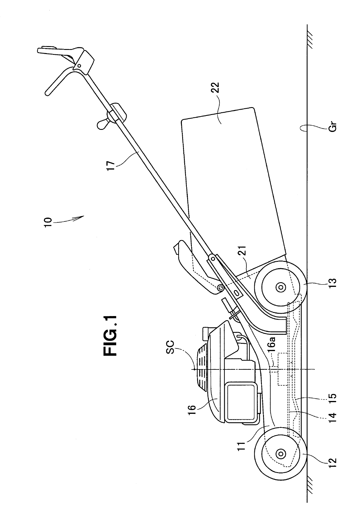
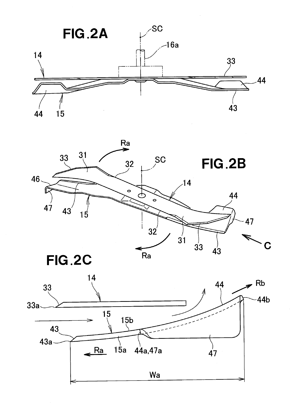
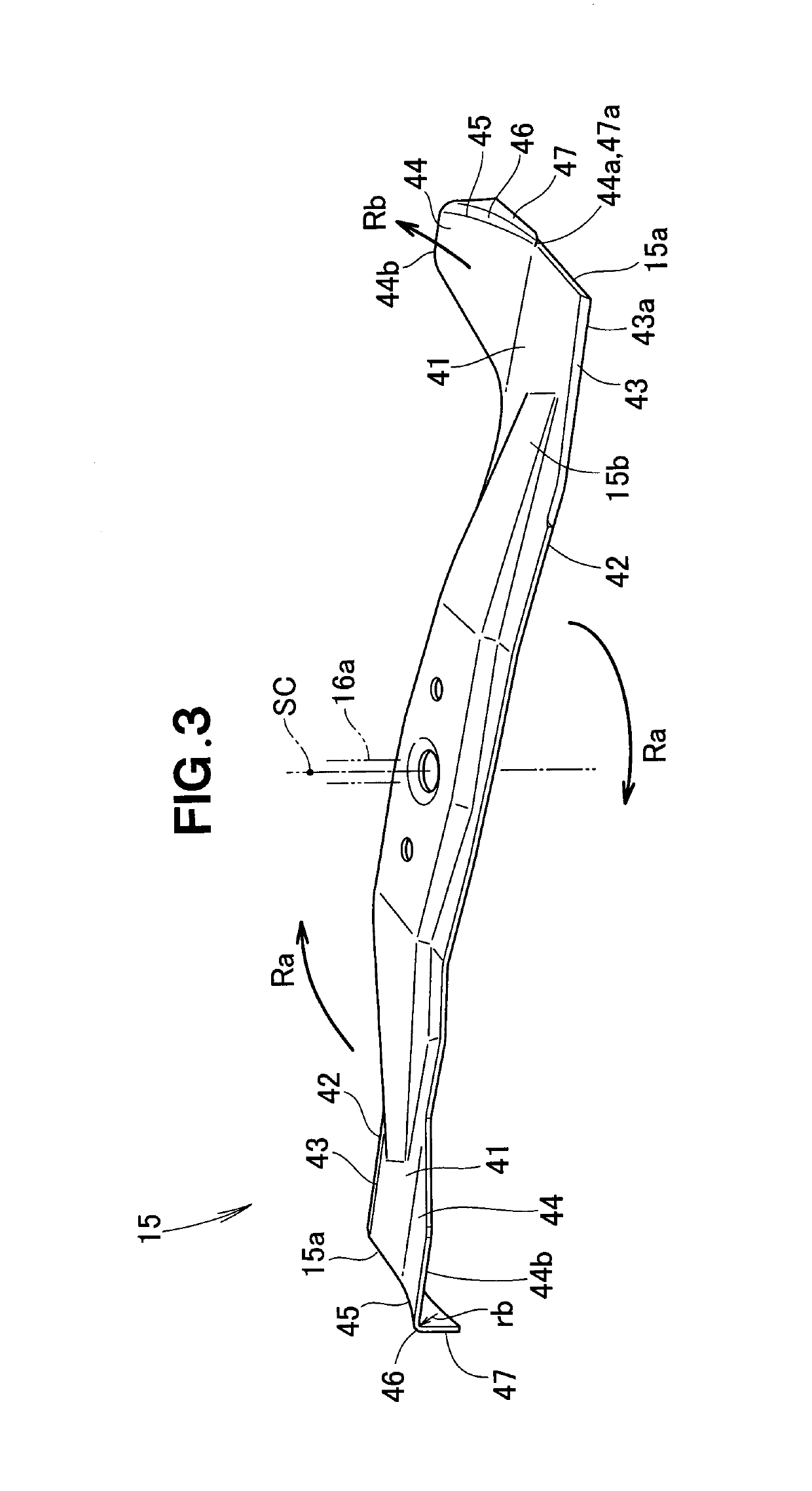
[0024]An embodiment of a lawn mower of the present invention will be described hereinbelow with reference to FIGS. 1 to 8. Note that, in the following description, the terms “left”, “right”, “upper”, “lower” etc. are used to refer to directions as viewed from a human operator operating the lawn mower.

[0025]As shown in FIG. 1, the lawn mower 10 of the present invention is a walk-behind, self-propelled working machine, which includes: a housing 11; left and right front wheels 12 provided on a front section of the housing 11; left and right rear wheels 13 provided on a rear section of the housing 11; upper and lower cutter blades 14 and 15 accommodated in a middle interior section of the housing 11; an engine (power source) 16 provided on an upper portion of the housing 11; and an operating handle 17 extending rearward from the housing 11. Note that, although the power source 16 will be described hereinbelow as being the engine, it may for example be an electric motor rather than being...


PUM


Abstract

A lawn mower includes a cutter blade that is an elongated member extending in opposite horizontal directions with respect to a vertical rotation shaft. The cutter blade includes, on each of its longitudinally opposite end portions, a blade section formed along the front edge, in a rotating direction of the cutter blade, of the end portion, and an air lift section extending from the front edge while curving rearward and upward. The air lift section has a vertical downward wing formed integrally thereon and extending downward via a bent section that is bent downward from at least a rear half portion, in the rotating direction, of an outer peripheral edge of the air lift section. The bent section has a radius set to gradually increase as the air lift section curves rearward and upward in the rotating direction.

Description

FIELD OF THE INVENTION[0001]The present invention relates to a rotary lawn mower with an improved cutter blade.BACKGROUND OF THE INVENTION[0002]Among the conventionally-known rotary lawn mowers are ones which cut grass by rotating a cutter blade, accommodated in a downwardly-opening housing, along the grass on a lawn. The rotation of the cutter blade would produce unwanted noise sound, and thus, improvement of cutter blades has been under way with a view to suppressing unwanted noise of the lawn mowers. One example of such lawn mowers is disclosed in Japanese Patent Application Laid-Open Publication No. 2006-67918 (hereinafter referred to as “Patent Literature 1”).[0003]The lawn mower disclosed in Patent Literature 1 includes a rotation shaft extending in a vertical (up-down) direction in a housing, and upper and lower cutter blades accommodated within the housing for rotation about the rotation shaft. The upper cutter blade has a blade section formed along the front edge, in the ro...

Claims


Application Information

Patent Timeline
Patent Type & Authority Patents(United States)
IPC IPC(8): A01D34/73A01D34/68A01D34/82A01D101/00
CPCA01D34/826A01D34/73A01D34/68A01D2101/00
Inventor KURIOKA, SHUNSUKETSURUOKA, SHINGO
Owner HONDA MOTOR CO LTD
Why Eureka
Try Eureka