MEMS device

a technology of mems and stoppers, which is applied in the direction of acceleration measurement using interia forces, instruments, coatings, etc., can solve the problems of affecting the function of the mems device, affecting the movement of the member or the stopper, etc., and achieves the effect of reducing the likelihood of damage and suppressing the stiction

Active Publication Date: 2019-05-14
MURATA MFG CO LTD
View PDF16 Cites 2 Cited by
  • Summary
  • Abstract
  • Description
  • Claims
  • Application Information

AI Technical Summary

Benefits of technology

[0008]In view of the foregoing design limitations in conventional MEMS devices, an object of the present disclosure is to provide a MEMS device that can suppress stiction and is also less likely to be damaged during operation.
[0010]Preferably, the MEMS device includes the impact alleviation mechanism in which the movable member and the fixed member abut at the elongate protruding portion. Accordingly, a contact area of the movable member and the fixed member via the impact alleviation mechanism is small, and stiction can be suppressed. Furthermore, in the exemplary MEMS device, the impact alleviation mechanism has the elongate protruding portion and the stopper portion configured such that in response to an increased collision force between the movable member and the fixed member, an abutment area's outer edge position approaches the fixed side edge of the stopper portion more closely. As such, in an initial stage of a collision, the stopper portion can flexibly deform and alleviate the movable member's collision force and thus prevent brittle fracture (cracking and chipping) of the elongate protruding portion and the stopper portion. Moreover, in a later stage of the collision, an apparent spring constant can be increased to suppress the stopper portion's deformation and a resultant stress concentration, which thereby prevents the stopper portion's ductile fracture. Accordingly, the MEMS device can suppress stiction despite a reduced space and is also less likely to be damaged when it receives an impact.
[0012]Preferably, when the elongate protruding portion abuts against the fixed side edge of the stopper portion, the stopper portion does not abut against the fixed member or the movable member from which the stopper portion is fixed. Thus, when the elongate protruding portion abuts against the fixed side edge of the stopper portion, the stopper portion does not abut against the fixed member or the movable member from which the stopper portion protrudes, so that in a collision process, the stopper portion's deformation is not inhibited and the stopper portion's apparent spring constant can be increased continuously and smoothly.
[0013]Preferably, the elongate protruding portion is formed in a strip protruding from the other of the fixed member and the movable member and having side edges among which at least one of the side edges is fixed. As a result, the elongate protruding portion and the stopper portion can alleviate collision force of the movable member and the fixed member. This can more effectively prevent damage of the movable member and the fixed member during vibration.
[0014]Preferably, the elongate protruding portion or the stopper portion is formed to be integrated with the fixed member or the movable member. As a result, the elongate protruding portion and / or stopper portion can easily and reliably form the impact alleviation mechanism in which the elongate protruding portion or the stopper portion is fine and less likely to be damaged.
[0016]According to the disclosure herein, the MEMS device having said impact alleviation mechanism can suppress stiction and is also less likely to be damaged when it receives an impact.

Problems solved by technology

However, in the case of a MEMS device having a stopper as described above, when a device having mounted therein / thereon the MEMS device, for example, falls and an impact force acts thereon, the movable member may collide with the stopper violently and the movable member and / or the stopper may be damaged.
As a result, damage of the movable member and / or the stopper may impair the MEMS device's function.

Method used


Image

  • MEMS device
  • MEMS device
  • MEMS device

Examples


first embodiment

[0027][First Embodiment]

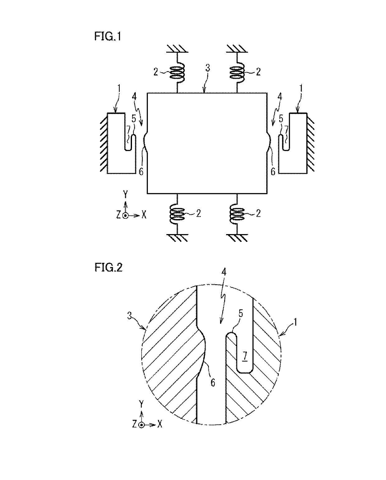
[0028]FIG. 1 shows a MEMS device including a fixed member 1 and a movable member 3 supported via a resilient body 2, such that the movable member 3 can vibrate in an x-y direction.

[0029]Fixed member 1 and one end of resilient body 2 are fixed to a base such as a substrate (not shown). Movable member 3 is supported by resilient body 2 with a gap between movable member 3 and the base.

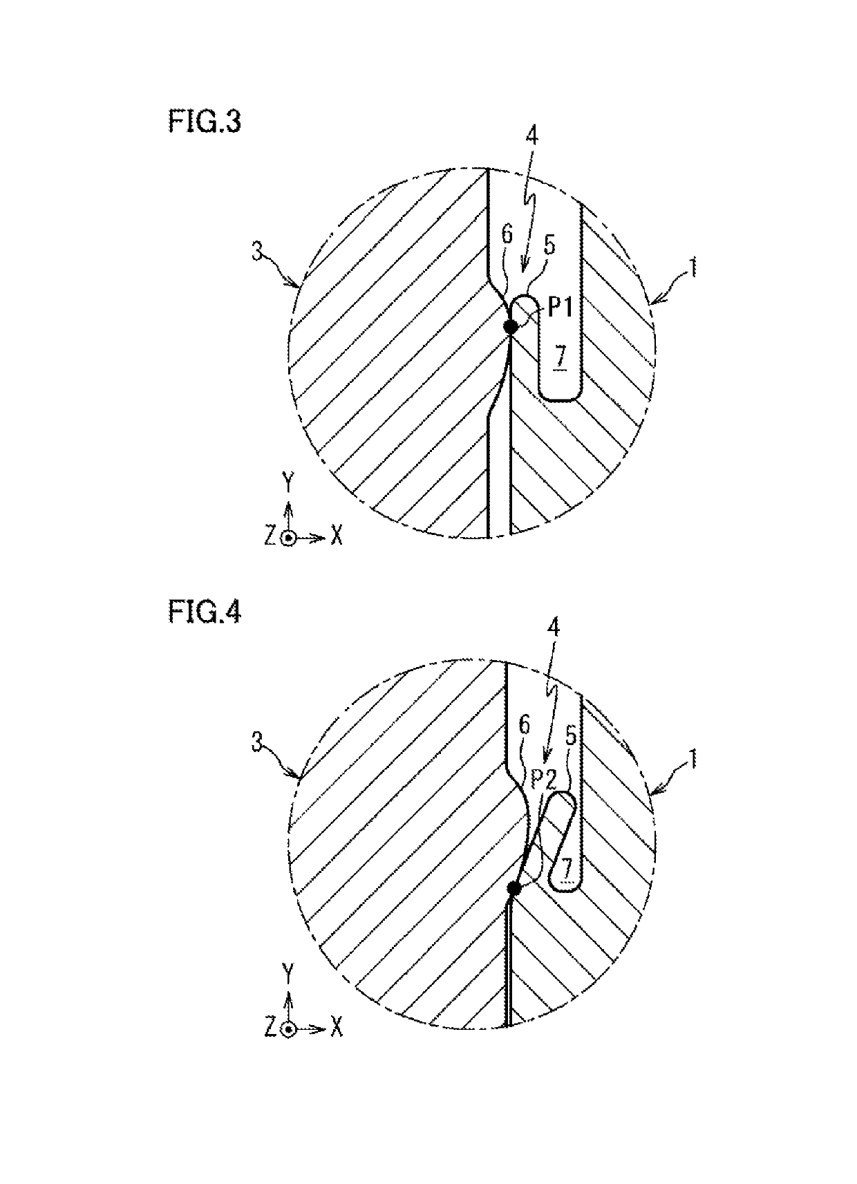
[0030]In operation, movable member 3 moves in the x direction against the resilient force of resilient body 2 and can thus collide with fixed member 1 in the x direction. An impact alleviation mechanism 4 is provided at a portion of fixed member 1 and movable member 3 where the two components may collide or contact each other during vibration of the movable member 3.

[0031]In one embodiment, fixed member 1, resilient body 2, and movable member 3 can be formed, for example, of silicon.

[0032]Moreover, fixed member 1, resilient body 2, and movable member 3 can have a thickness in a z d...

second embodiment

[0055][Second Embodiment]

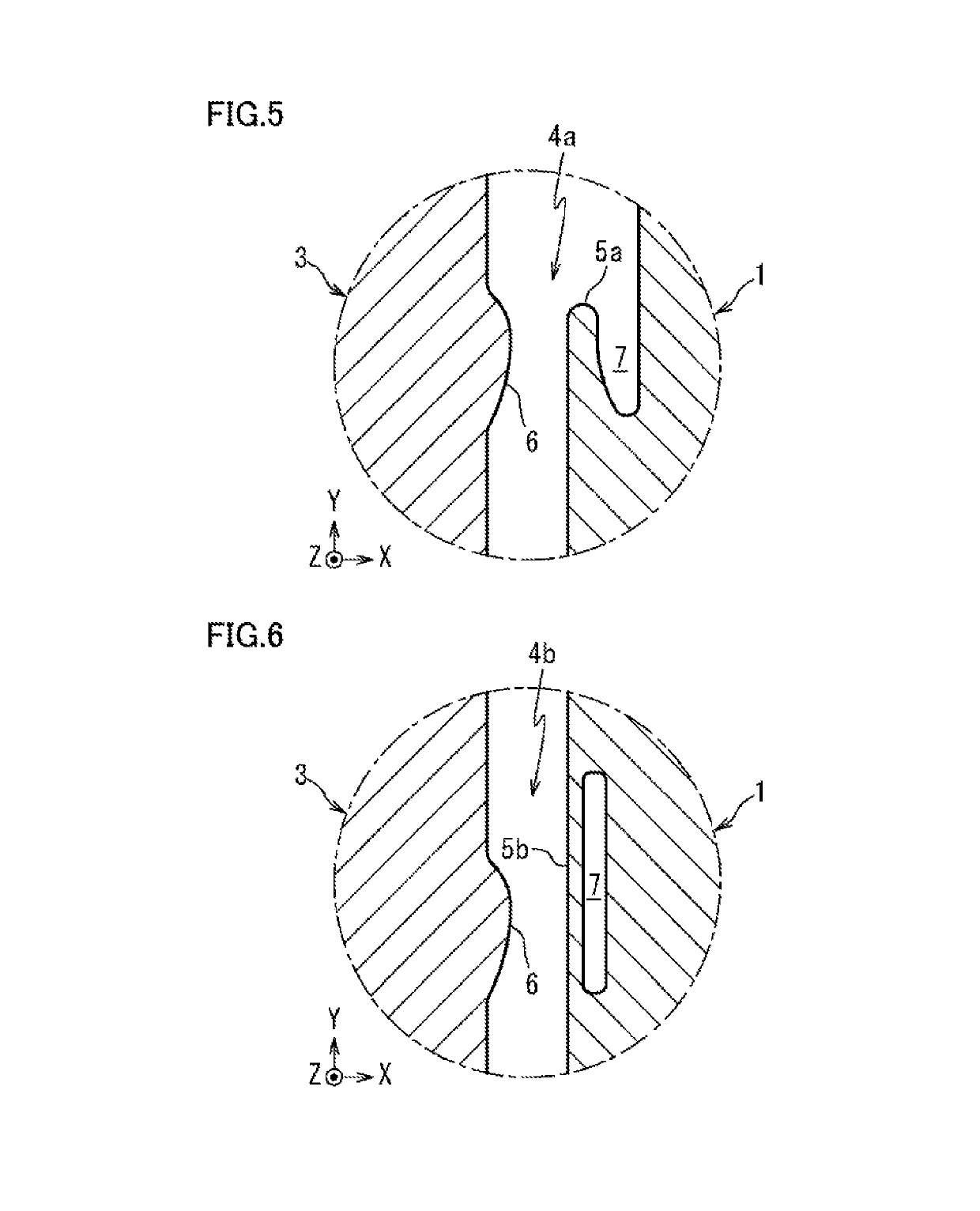
[0056]FIG. 5 illustrates an impact alleviation mechanism 4a that is applicable to the MEMS device of FIG. 1 as an alternative to impact alleviation mechanism 4 of FIG. 2.

[0057]As shown, impact alleviation mechanism 4a has a stopper portion 5a in the form of a strip provided to fixed member 1 to protrude in a direction (the y direction) substantially perpendicular to the collision direction (the x direction) and includes side edges among which one of them is fixed, and elongate protruding portion 6 provided to movable member 3 to protrude in the collision direction (the x direction). The configuration of elongate protruding portion 6 in impact alleviation mechanism 4a of FIG. 5 is similar to the shape and the like of elongate protruding portion 6 in impact alleviation mechanism 4 of FIG. 2. Accordingly, it will be not described again as such details are described above.

[0058]According to this embodiment, stopper portion 5a is formed in the form of a strip ext...

third embodiment

[0061][Third Embodiment]

[0062]FIG. 6 illustrates an impact alleviation mechanism 4b that is applicable to the MEMS device of FIG. 1 as an alternative to impact alleviation mechanism 4 of FIG. 2.

[0063]As shown, impact alleviation mechanism 4b has a stopper portion 5b in the form of a strip provided to fixed member 1 to protrude in a direction (the y direction) substantially perpendicular to the collision direction (the x direction) and having both side edges fixed, and elongate protruding portion 6 provided to movable member 3 to protrude in the collision direction (the x direction). Apart from this design variation, the configuration of elongate protruding portion 6 in impact alleviation mechanism 4b of FIG. 6 is similar in shape and the like of elongate protruding portion 6 in impact alleviation mechanism 4 of FIG. 2. Accordingly, it will be not described again as such details are described above.

[0064]As further shown, stopper portion 5b is formed in the form of a strip extending ...


PUM

PropertyMeasurementUnit
angleaaaaaaaaaa
angleaaaaaaaaaa
angleaaaaaaaaaa

Abstract

A MEMS device including a fixed member and a movable member supported via a resilient body. The MEMS device includes an impact alleviation mechanism provided at a position where the movable member and the fixed member collide during operation. The impact alleviation mechanism includes a stopper provided to either the fixed member or the movable member and that protrude to be parallel between sides of the two members with at least one side edge fixed to the respective member. Moreover, the impact alleviation mechanism includes an elongate protruding member provided on the other of the fixed member and the movable member. The elongate protruding member and the stopper are configured such that as collision force increases between the movable member and the fixed member during operation, an abutment area of an outer edge position of the elongate protruding member approaches the fixed side edge of the stopper.

Description

CROSS REFERENCE TO RELATED APPLICATIONS[0001]The present application is a continuation of PCT / JP2015 / 066006 filed Jun. 3, 2015, which claims priority to Japanese Patent Application No. 2014-116613, filed Jun. 5, 2014, the entire contents of each of which are incorporated herein by reference.TECHNICAL FIELD[0002]The present disclosure generally relates to a MEMS device, and, more particularly, to a MEMS device that suppresses stiction and is not easily damaged during operation.BACKGROUND ART[0003]In recent years, a device having a fine mechanical element formed by utilizing semiconductor manufacturing technology called MEMS (“Micro Electro Mechanical Systems”; hereinafter a “MEMS device”) has been developed, and implemented, for example, as a gyro sensor, an acceleration sensor, or the like.[0004]Such a MEMS device often includes a movable vibration member supported by a substrate via a resilient body. It is known that in a MEMS device including a movable member, the movable member m...

Claims


Application Information

Patent Timeline
Patent Type & Authority Patents(United States)
IPC IPC(8): G01P15/02H01L29/84G01C19/5769B81B3/00B81C1/00G01P15/08
CPCB81B3/0013B81B3/00B81C1/00968G01C19/5769H01L29/84G01P15/02G01P2015/0871B81B2201/0235B81B2201/0242B81B3/001B81B3/0051
Inventor MATSUOKA, JUNYATSUJI, NOBUAKIUEYA, YUKIOKAMI, TSUYOSHIMIZOTA, TAKASHI
Owner MURATA MFG CO LTD
Why Eureka
Try Eureka