
Externally supported anastomosis

an anastomosis and external support technology, applied in the field of external support anastomosis, can solve the problems of inability to achieve long-term flow stability

Active Publication Date: 2019-05-21
AVENU MEDICAL
View PDF11 Cites 1 Cited by
  • Summary
  • Abstract
  • Description
  • Claims
  • Application Information

AI Technical Summary

Benefits of technology

The present invention is about a method for creating a fistula (a connection between two vessels) using a fixing agent. The method aims to reduce operating time, create consistent and repeatable fistulas, and stabilize long term flow in the veinal vessels. The fixing agent serves three purposes. The first purpose is to hold the vessels in position, minimizing leaking and healing required for a productive fistula. The second purpose is to seal the surrounding tissue to prevent any leaks from spreading and creating a hematoma. The third purpose is to limit the expansion of the fistula over time, ensuring long term flow stability.

Problems solved by technology

There are circumstances where too much flow may be encountered and smaller vessels are targeted.
These thin walls can expand over periods of time and the flow can increase to undesirable rates.
Flows can increase to the point that they overload the right side of the heart, potentially causing heart failure.

Method used


Image

  • Externally supported anastomosis
  • Externally supported anastomosis
  • Externally supported anastomosis

Examples


Embodiment Construction

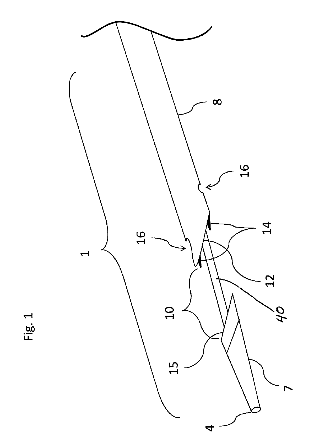
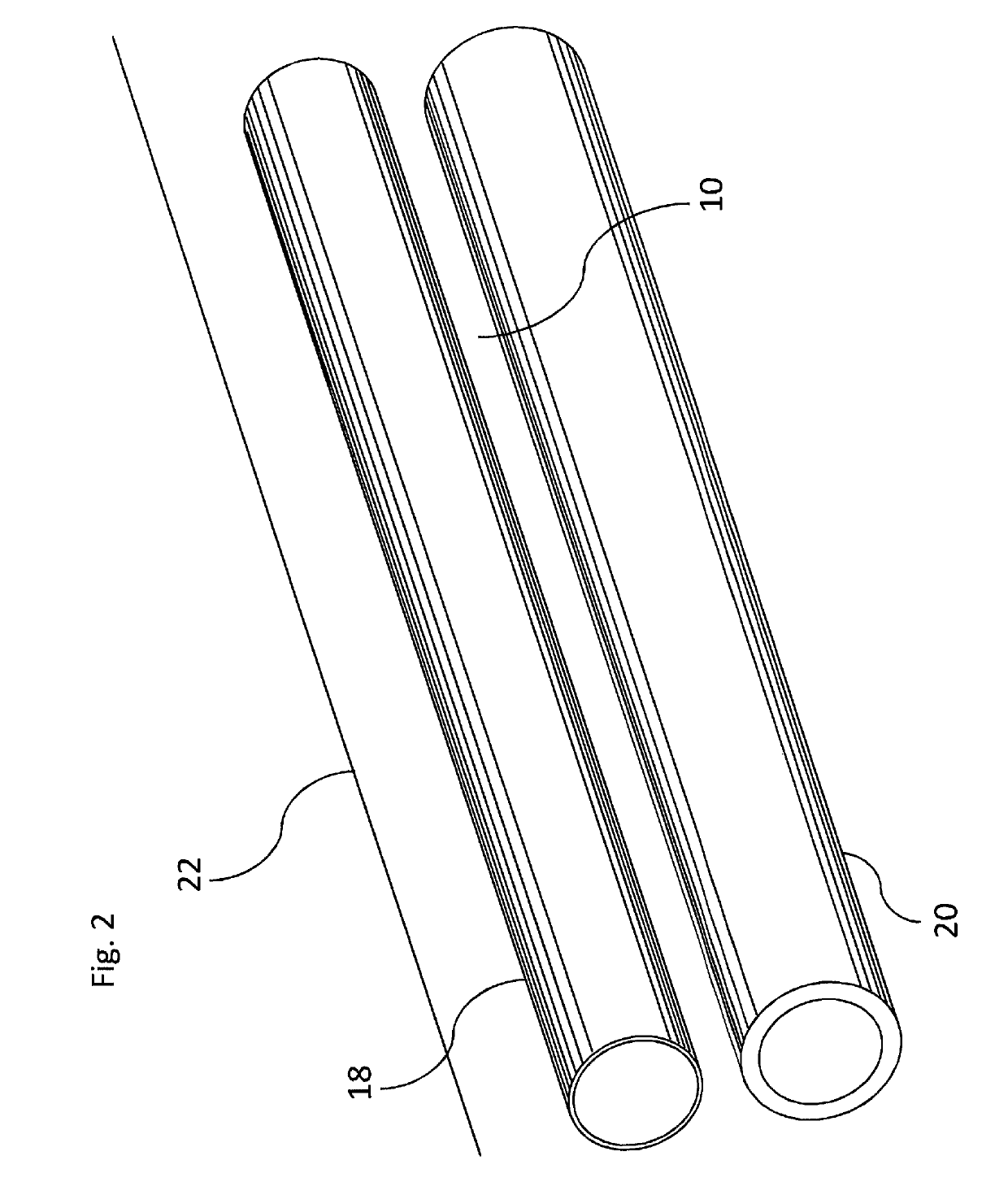
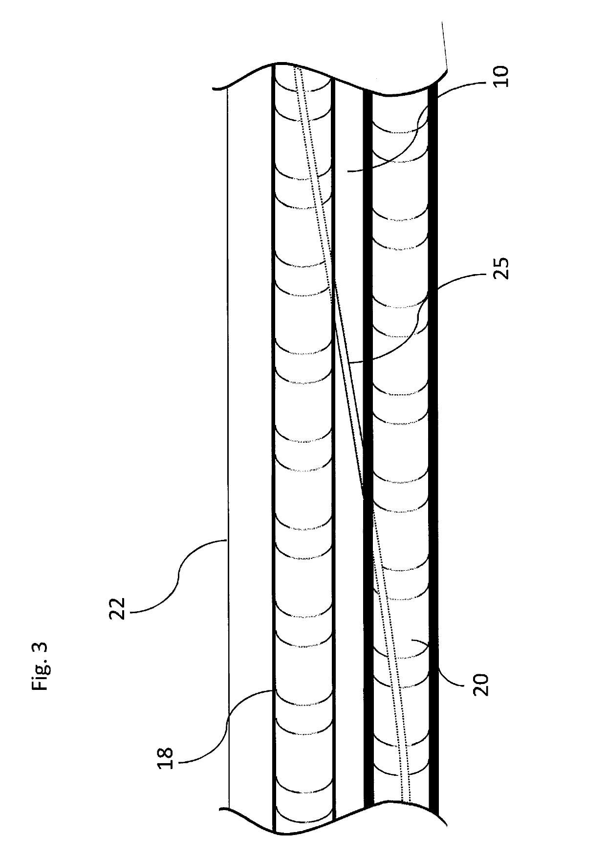
[0043]Referring now more particularly to the drawings, the inventive system is grounded by a basic need to bring two vessels together in order to form a fistula. In one embodiment of the present invention, the device is embodied by a catheter 1 (FIG. 1). The catheter 1 is guided by a guidewire through a distal port 4 that accesses a lumen that extends through the entire length of the catheter. The catheter has a distal jaw or distal tip 7 that accesses a second, distal vessel 20 (FIG. 2), leaving vessel walls from both vessels 18, 20 (FIG. 2) in a gap 10, as well as a proximal jaw or proximal base 8. A proximal jaw face 12 engages a distal inner wall of the first vessel 18, while a distal jaw face 15 engages the proximal inner wall of the second vessel 20. Ports 16 enable the catheter to inject a stabilizing material into the extra-vascular space. A cutting mechanism 14 serves to punch the orifice between the vessels to create the fistula.

[0044]As noted above, FIG. 2 illustrates an ...


PUM


Abstract

A device for creating a fistula between blood vessels operates in conjunction with a guidewire to locate and position itself so that it straddles both vessels and is able to draw them together. A fixing agent is released either from within the device or from an external needle, or both, into the procedural site. The fixing agent functions to hold the relative position of the two vessels, to seal the surrounding tissue so that any leaks that do occur don't spread into the tissue to create a hematoma, and to limit expansion of the fistula. After the vessels are in close proximity to each other and the fixing agent is applied, the device of the invention employs a cutting mechanism which opens a portal between the two vessels.

Description

[0001]This application claims the benefit under 35 U.S.C. 119(e) of the filing date of Provisional U.S. Application Ser. No. 61 / 939,376, entitled Externally Supported Anastomosis, filed on Feb. 13, 2014, which application is expressly incorporated herein by reference, in its entirety.BACKGROUND OF THE INVENTION[0002]In the body, various fluids are transported through conduits throughout the organism to perform various essential functions. Blood vessels, arteries, veins, and capillaries carry blood throughout the body, carrying nutrients and waste products to different organs and tissues for processing. Bile ducts carry bile from the liver to the duodenum. Ureters carry urine from the kidneys to the bladder. The intestines carry nutrients and waste products from the mouth to the anus.[0003]In medical practice, there is often a need to connect conduits to one another or to a replacement conduit to treat disease or dysfunction of the existing conduits. The connection created between co...

Claims


Application Information

Patent Timeline
Patent Type & Authority Patents(United States)
IPC IPC(8): A61B17/11
CPCA61B17/11A61B2017/1107A61B2017/1139A61B17/00491A61B17/32053
Inventor FOERSTER, SETH ARNOLDKELLERMAN, BRAD MATHEWRITCHART, MARK ANDREWMANN, JUSTIN KELLOGG
Owner AVENU MEDICAL
Learn More