Cable armour stripping unit

a technology of armour and cable, which is applied in the direction of cables, insulated conductors, conductors, etc., can solve the problems of increasing the risk of cutting too deeply, difficult to operate cutting tools with the necessary degree of precision, and damage to the inner layer, etc., to improve the cutting precision

Inactive Publication Date: 2019-05-21
SIEMENS GAMESA RENEWABLE ENERGY AS
View PDF60 Cites 0 Cited by
  • Summary
  • Abstract
  • Description
  • Claims
  • Application Information

AI Technical Summary

Benefits of technology

[0008]The inventive cable armour stripping unit has a number of advantages over the conventional techniques. Since the cutter arrangement is mounted on the frame, and the cable can be fed relative to the frame as well as rotated relative to the cutter arrangement, it is possible to make controlled incisions into the outer armouring layer. The speed of cutting as well as the direction of cutting can be very precisely controlled. This reduces the risk of cutting too deeply into the outer layers, which would result in costly damage to the inner jacket and possibly also to the inner cable bundle. Equally, the inventive cable armour stripping unit avoids insufficiently deep cuts and repetitions of the cutting step.
[0010]An advantage of the method according to embodiments of the invention is that the removal of the outer armouring can be effected relatively quickly and very precisely, thus reducing the hazards associated with manual removal of the armouring.
[0018]To improve the precision of the cutting, the cutter arrangement preferably comprises a pressure sensor arranged to sense a pressure exerted on the saw blade as it cuts through the armouring. The pressure sensor can report pressure measurements or values to the saw control module, which can react accordingly. For example, a sudden decrease in pressure can indicate that the saw blade has penetrated through an outer armouring layer and has reached another, inner armouring layer. The saw control module can then determine the depth of the outer armouring layer and can control the saw blade(s) accordingly. Such a pressure sensor may be incorporated in a hydraulic system that is part of the power supply to a saw blade.
[0019]Two saw blades can be controlled independently to achieve various cutting patterns, depending on the type of armouring to be cut. For example, two saw blades can be diametrically opposed about the transmission cable, and tilted at the pitch angle of the outermost armouring layer. The control unit can set the cutting depth for the blades, i.e. the depth of the outermost armouring layer. The vertical feeder effects a longitudinal movement of the cable relative to the frame, and the rotation means effects a rotation of the cutting tools about the cable at a speed that is based on the pitch angle of the outermost armouring layer. In this arrangement, two circular saw blades effectively cut two helical bands of the outermost armouring.
[0020]In another example, a transmission cable may have an outermost armouring layer with a positive pitch angle and another inner armouring layer with a negative pitch angle. The outermost armouring layer may be more resilient than the inner armouring layer. To remove these layers, the saw control module of the inventive armour stripping unit tilts a first circular saw blade at an angle to match the positive pitch angle of the outermost layer, and tilts the second circular saw blade at a negative pitch angle to match the pitch angle of the inner layer. The control module can also individually control the pressure exerted by each saw on the armouring layer that it is working on, for example based on feedback from a number of pressure sensors, and can also individually control the cutting speed of each saw. In this way, several layers of armouring can be removed essentially simultaneously. Of course, it will be understood that a certain amount of an outermost armouring layer must be removed by a first saw before a second saw can commence cutting the next inner armouring layer. An armour stripping unit with three or more saw blades is also conceivable, so that three more armouring layers can be removed simultaneously. In any case, the control unit can control the saw blades and the translation / rotation means to execute any sequence of steps required to achieve a complete removal of the armouring layers to reach the depth of the inner jacket.
[0022]Even after the saw blades have cut into the armouring, the rigidity and thickness of the armouring means that it will generally remain in place about the inner jacket. Therefore, in a particularly preferred embodiment of the invention, the cable stripping unit comprises an armour pry tool realized to pry a cut armour layer from the cable. Such a tool can comprise a flat blade or lever that can be pushed between an outer cut layer and an inner layer in order to prise away the cut layer. For example, if an outer armouring layer is being cut to give a helical band, the pry tool can simultaneously prise the cut band away from the inner jacket as the cable is moved relative to the frame.

Problems solved by technology

It is important not to insert the cutting tool too far into the armouring, otherwise the inner layers may sustain damage.
Equally, it is important to make sufficiently deep incisions, otherwise the cutting step must be repeated, thereby increasing the risk of cutting too deeply.
However, the material strength of the outer layers and the armouring can make it difficult to operate the cutting tools with the necessary degree of precision.
Another problem arises from the difficulty of handling the heavy and unwieldy transmission cable in a confined space such as the transition piece of an offshore wind turbine.
For these reasons, the step of manually removing armouring from transmission cables is presently a hazardous and costly procedure.
This reduces the risk of cutting too deeply into the outer layers, which would result in costly damage to the inner jacket and possibly also to the inner cable bundle.

Method used


Image

  • Cable armour stripping unit
  • Cable armour stripping unit
  • Cable armour stripping unit

Examples


Embodiment Construction

[0035]In the diagrams, like numbers refer to like objects throughout. Objects in the diagrams are not necessarily drawn to scale.

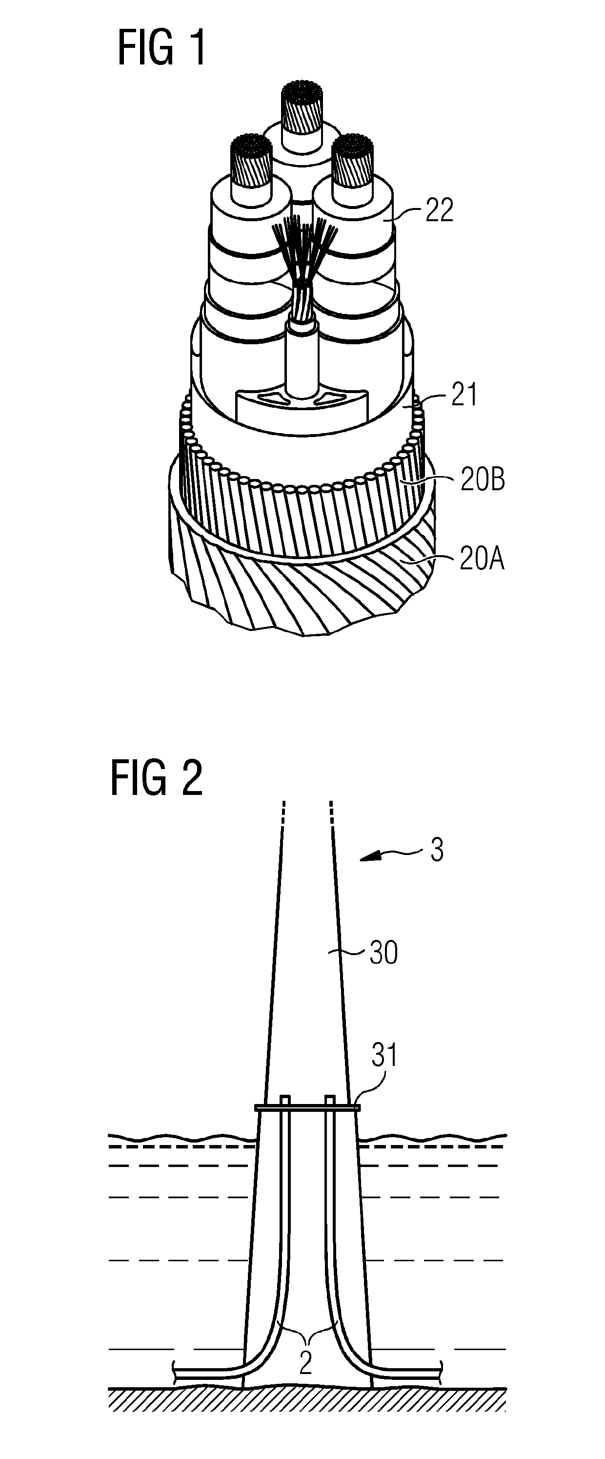
[0036]FIG. 1 shows a transmission cable 2 of the type used to transport electrical power from an offshore wind power facility. The transmission cable 2 comprises a number of conductors 22 arranged in a bundle contained within an inner jacket 21. This in turn is enclosed by a number of protective outer layers 20A, 20B. In this exemplary embodiment, the outermost armouring layer 20A comprises steel wires embedded in a nylon or bitumen mantle; and an inner armouring layer 20B comprises an arrangement of slanted metal wires. The wires in an armouring layer are generally arranged at a pitch angle θ to ensure that the transmission cable cannot be twisted. Here, the pitch angle θB of the inner armouring layer 20B is positive, while the pitch angle θA of the outer armouring layer 20A is negative. Having multiple armouring layers with opposing pitch angle direction...


PUM


Abstract

A cable armour stripping unit is provided, including a frame configured to accommodate a transmission cable having a plurality of armoured outer layers arranged about an inner sheath enclosing a plurality of conductors and to hold a cutter arrangement including at least one cutting tool arranged to cut into an armoured outer layer of the cable; a vertical feed arrangement configured to effect a translation of the frame relative to the cable, and a rotation arrangement configured to effect a rotation of the frame relative to the cable. A method of stripping armour from a transmission cable is also provided.

Description

CROSS-REFERENCE TO RELATED APPLICATION[0001]This application claims priority to European Application No. 16172232.7 having a filing date of May 31, 2016 the entire contents of which are hereby incorporated by reference.FIELD OF TECHNOLOGY[0002]The following describes a cable armour stripping unit, and a method of stripping armour from a transmission cable.BACKGROUND[0003]To transport electrical energy from an offshore facility, it is usual to use a transmission cable that can be laid on the seabed. Such a transmission cable generally has an inner bundle which comprises a number of conductors for multi-phase power transmission, and which might also enclose a data communication line. This inner bundle is screened and contained in a jacket, which in turn is protected by a number of outer layers. Usually, several of these outer layers enclose some kind of armouring, for example a close arrangement of copper or galvanized steel wires. These can form a separate layer between sheaths and / o...

Claims


Application Information

Patent Timeline
Patent Type & Authority Patents(United States)
IPC IPC(8): H02G1/12
CPCH02G1/1265H02G1/127H02G1/1297H02G1/1268H02G1/1231H01R43/28H01B7/38H01B11/00H01B15/005
Inventor SOERENSEN, JOHNNY
Owner SIEMENS GAMESA RENEWABLE ENERGY AS
Why Eureka
Try Eureka