Electrical machine with superconducting coils

a superconducting coil and electric machine technology, applied in the field of electric machines, can solve the problems of increasing reducing the efficiency of superconducting coils, so as to improve the capacity to maintain the temperature condition and reduce the cost of superconducting coils. the effect of efficient and rapid cooling

Active Publication Date: 2019-05-21
AIRBUS
View PDF12 Cites 2 Cited by
  • Summary
  • Abstract
  • Description
  • Claims
  • Application Information

AI Technical Summary

Benefits of technology

[0020]In this arrangement, the electromechanical machine benefits, after cooling, from the advantages provided by electrical conductors, particularly coil conductors, which are superconducting without any external means for maintaining the temperature below the critical temperature, using the mass of the functional part as a heat sink.
[0048]a step for determining a capacity for storing thermal energy in static form by accumulation in the elements of the functional part of the electromechanical machine, taking into consideration the critical temperature Tc of the superconducting material and the temperature of the cryogenic fluid used, and for optimizing the internal design of the active part so as to maximize said storage capacity;

Problems solved by technology

This constraint resulted in the development of machines with superconducting coils limited to static applications, such as for example coils used in particle accelerators or magnetic resonance imaging devices, and more recently for storing energy in magnetic form, for which the continuous cooling required may be achieved without any insurmountable difficulty by installations that are heavy and complex to implement.
When the machine is onboard a vehicle, in addition to the cumbersome necessity of carrying a sufficient quantity of gas, it is necessary to provide distribution and regulating means whose operation at a cryogenic temperature is more complex than in the case of systems operating at ambient temperature.
Such cryogenic cold-generating devices are known, but they are still heavy and bulky and must be supplied with energy in order to produce the required cold.
In cases where such devices are used, a malfunction of the cooling system generally results in an immediate shutdown of the machine being cooled unless redundant cooling devices are provided.
The known methods are therefore disadvantageous and are unsatisfactory for onboard machines when, in particular, volume, mass, and reliability are essential criteria, such as for example in the case of applications onboard aircraft.

Method used


Image

  • Electrical machine with superconducting coils
  • Electrical machine with superconducting coils

Examples


Embodiment Construction

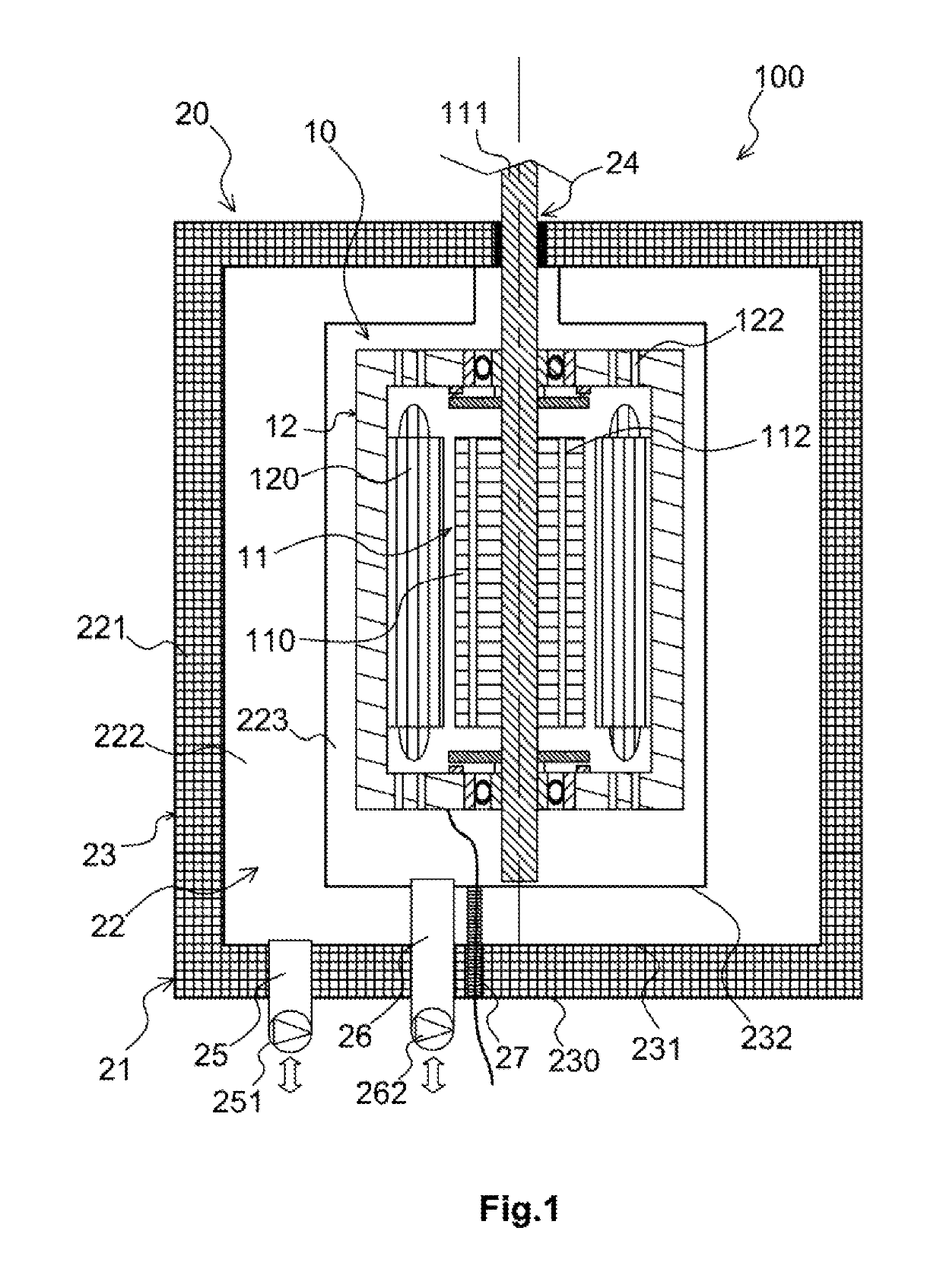
[0054]The various components and elements of the electromechanical machine are not shown to scale.

[0055]In FIG. 1, the accessory elements, mounts, electrical cables, sensors, etc., are not shown.

[0056]The electromechanical machine 100, schematically illustrated in FIG. 1, comprises a functional part 10 and comprises a thermal control system 20 for regulating a temperature of said functional part.

[0057]The functional part 10 performs the expected functions of the electromechanical machine 100, typically the functions of an electric motor and / or of an electric generator, in this case comprising a rotor 11.

[0058]In its general principals and its structure, the functional part 10 is similar to that of the known electromechanical machines comprising a moving part, in this case a rotor 11, and a stator 12. It also comprises, in a known way, magnetic parts, for example magnets and / or parts made of magnetic materials, and comprises at least one electrical conductor, for example a coil made ...


PUM


Abstract

An electromechanical machine includes at least one coil made from a material that becomes electrically superconducting when its temperature is below a critical temperature. A functional part is contained in an internal volume of a thermally insulating and fluid-tight enclosure of the machine. A wall of the insulating enclosure is traversed in a fluid-tight fashion by at least one shaft for transmitting mechanical power between the functional part located in the internal volume of the insulating enclosure and a space outside the insulating enclosure. The functional part can be used as a heat sink, pre-cooled to maintain the temperature conditions for maintaining superconductivity inside the insulating enclosure.

Description

RELATED APPLICATIONS[0001]This application is a § 371 application from PCT / EP2013 / 077104 filed Dec. 18, 2013, which claims priority from French Patent Application No. 12 62478 filed Dec. 20, 2012, each of which is herein incorporated by reference in its entirety.TECHNICAL FIELD OF THE INVENTION[0002]The present invention belongs to the field of electromechanical machines, motors, or generators whose coils are maintained at very low temperatures during operation.[0003]More particularly, the invention relates to an electromechanical machine whose coil windings are maintained at temperatures low enough to enable these coils to function as superconductors.BACKGROUND OF THE INVENTION[0004]Electrical superconductivity is a well-known phenomenon that arises in certain materials and makes their electrical resistivity practically zero.[0005]This property of certain materials is particularly advantageous because it results in the ability to produce windings for generating magnetic fields that...

Claims


Application Information

Patent Timeline
Patent Type & Authority Patents(United States)
IPC IPC(8): H02K9/19H02K55/00H02K9/20
CPCH02K9/19H02K55/00H02K9/20Y02E40/62Y02E40/60
Inventor SMAOUI, HICHEMNESPOULOUS, CHARLESRECHAIN, BRUNOJOUBERT, EMMANUEL
Owner AIRBUS
Why Eureka
Try Eureka