Fuel injection valve

a fuel injection valve and valve body technology, applied in the direction of valve operating means/release devices, machines/engines, mechanical equipment, etc., can solve the problems of aging, seat diameter change, and possible deviation of the location of the seal portion, so as to stabilize the seat diameter, reduce the effect of aging and stabilizing the fuel injection quantity

Active Publication Date: 2019-05-28
DENSO CORP
View PDF33 Cites 3 Cited by
  • Summary
  • Abstract
  • Description
  • Claims
  • Application Information

AI Technical Summary

Benefits of technology

[0009]It is an objective of the present disclosure to provide a fuel injection valve that reduces a change in a fuel injection quantity caused by aging and reliably supplies a required quantity of fuel, which needs to be injected, to an injection hole.
[0013]In the fuel injection valve of the present disclosure, when the boundary between the first seal portion and the second seal portion is lifted away from or is seated against the valve seat, the injection hole is opened or closed, respectively. In this way, even when the first seal portion and the second seal portion are resiliently deformed through the contact with the valve seat, the contact location between the boundary and the valve seat is unchanged. Therefore, it is possible to stabilize the seat diameter. Thus, the fuel injection quantity can be stabilized.
[0014]Furthermore, in the fuel injection valve of the present disclosure, at least one of the first outer wall and the second outer wall has the cross section, which includes the central axis and forms the curved line. At least one of a gap, which is formed between the first outer wall and an inner wall of the housing, and a gap, which is formed between the second outer wall and the inner wall of the housing, is increased in comparison to a case where both of the first outer wall and the second outer wall are tapered. Therefore, when the boundary is lifted away from the valve seat, a required quantity of fuel, which needs to be injected, can be reliably supplied to the injection hole.
[0015]Furthermore, in the fuel injection valve of the present disclosure, the first outer wall is formed such that in the cross section, which includes the central axis, the angle defined between the tangent line, which is tangent to the first outer wall at the boundary, and the central axis is larger than the angle defined between the tangent line, which is tangent to the second outer wall at the boundary, and the central axis. In this way, in comparison to a case where the outer wall of the seal portion, which is contactable against the valve seat, is shaped into a form of a spherical surface, a foreign object, which enters a gap between the boundary and the valve seat, can be removed by crashing the foreign object.
[0016]As discussed above, the fuel injection valve of the present disclosure stabilizes the seat diameter, so that the change in the fuel injection quantity caused by the aging can be reduced, and the foreign object, which enters the gap between the boundary and the valve seat, can be removed. Also, the fuel injection valve of the present disclosure increases the gap between the second outer wall, which is located on the upstream side of the boundary, and the inner wall of the housing, or the gap between the first outer wall, which is located on the downstream side of the boundary, and the inner wall of the housing, so that the required quantity of fuel, which needs to be injected, can be reliably supplied to the injection hole.

Problems solved by technology

However, due to resilient deformation of the seal portion, the location of the seal portion will deviate.
Therefore, every time fuel is injected, the seat diameter may possibly change.
Furthermore, in the case where the outer wall of the seal portion is shaped into the form of the spherical surface, there may be a possibility of that a foreign object is continuously captured between the outer wall of the seal portion and the valve seat and thereby cannot be removed.
Thus, it is difficult to ensure the fluid tightness in the valve closing time of the fuel injection valve.
Therefore, the required quantity of fuel, which is required for the injection, cannot be supplied to the injection hole.

Method used


Image

  • Fuel injection valve
  • Fuel injection valve
  • Fuel injection valve

Examples


first embodiment

(First Embodiment)

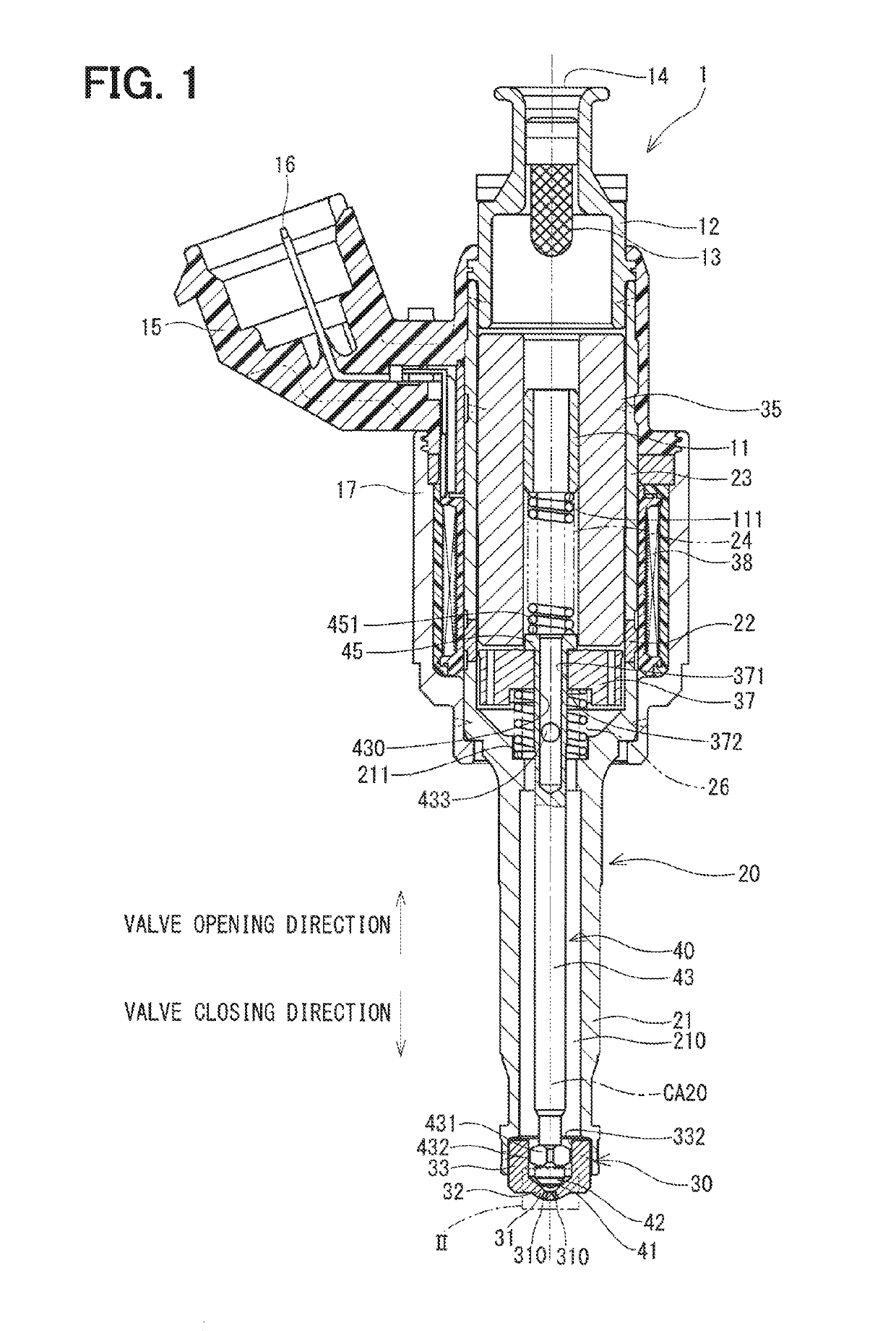
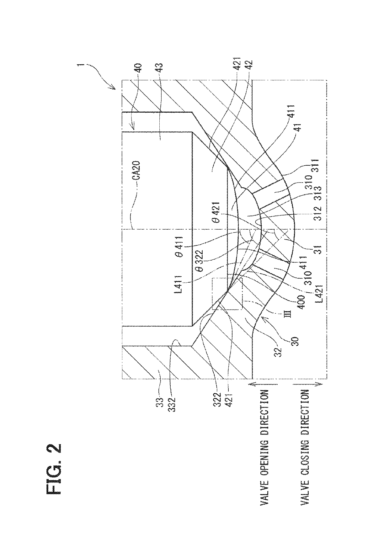
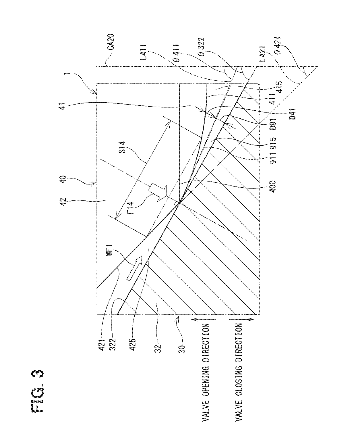
[0025]A fuel injection valve 1 according to a first embodiment of the present disclosure will be described with reference to FIGS. 1 to 3. FIGS. 1 to 3 indicate a valve opening direction, which is a direction of lifting a needle 40 away from an inner wall (serving as a valve seat) 322, and a valve closing direction, which is a direction of seating the needle 40 against the inner wall 322.

[0026]The fuel injection valve 1 is used in a fuel injection apparatus of, for example, a direct injection gasoline engine (not shown) and injects gasoline (serving as fuel) under a high pressure. The fuel injection valve 1 includes a housing 20, the needle 40, a movable core 37, a stationary core 35, a coil 38, a first spring (serving as an urging member) 24 and a second spring 26.

[0027]As shown in FIG. 1, the housing 20 includes a first tubular member 21, a second tubular member 22, a third tubular member 23 and an injection nozzle 30. The first tubular member 21, the second tubu...

second embodiment

(Second Embodiment)

[0064]Next, a fuel injection valve according to a second embodiment of the present disclosure will be described with reference to FIG. 4. The second embodiment differs from the first embodiment with respect to the shape of the outer wall of the first seal portion and the shape of the outer wall of the second seal portion. In the following discussion, the parts, which are substantially the same as those of the first embodiment, will be indicated by the same reference signs and will not be described for the sake of simplicity. FIG. 4, which corresponds to FIG. 2 of the first embodiment, indicates the valve opening direction, which is a direction of lifting a needle 50 away from the inner wall 322, and the valve closing direction, which is a direction of seating the needle 50 against the inner wall 322.

[0065]In the fuel injection valve 2 of the second embodiment, the needle 50 includes a first seal portion 51, a second seal portion 52, the shaft portion 43 and the fl...

third embodiment

(Third Embodiment)

[0071]Next, a fuel injection valve according to a third embodiment of the present disclosure will be described with reference to FIG. 5. The third embodiment differs from the first embodiment with respect to the shape of the outer wall of the second seal portion. In the following discussion, the parts, which are substantially the same as those of the first embodiment, will be indicated by the same reference signs and will not be described for the sake of simplicity. FIG. 5, which corresponds to FIG. 2 of the first embodiment, indicates the valve opening direction, which is a direction of lifting a needle 60 away from the inner wall 322, and the valve closing direction, which is a direction of seating the needle 60 against the inner wall 322.

[0072]In the fuel injection valve 3 of the third embodiment, the needle 60 includes the first seal portion 41, a second seal portion 62, the shaft portion 43 and the flange portion 45. In the third embodiment, when the needle 60...


PUM


Abstract

A needle includes a first seal portion, which is formed at an end portion of the needle located on a side where an injection hole is placed, and a second seal portion, which is formed on a side of the first seal portion where a stationary core is placed. When a boundary between a first outer wall of the first seal portion and a second outer wall of the second seal portion is lifted away from or is seated against an inner wall, the injection hole is opened or closed. Thereby, a seat diameter of the boundary and the inner wall is stabilized, and a change in a fuel injection quantity caused by aging can be reduced. Furthermore, the first outer wall of the first seal portion is shaped into a form of a spherical surface.

Description

[0001]This application is the U.S. national phase of International Application No. PCT / JP2015 / 005172 filed on Oct. 13, 2015 which designated the U.S. and claims priority to Japanese Patent Application No. 2014-216147 filed on Oct. 23, 2014, the entire contents of each of which are hereby incorporated by referenceCROSS REFERENCE TO RELATED APPLICATION[0002]This application is based on and incorporates herein by reference Japanese Patent Application No, 2014-216147 filed on Oct. 23, 2014.TECHNICAL FIELD[0003]The present disclosure relates to a fuel injection valve that injects fuel in an internal combustion engine (hereinafter, referred to as an engine).BACKGROUND ART[0004]Previously, there is known a fuel injection valve that opens and closes an injection hole of a housing through reciprocation of a needle to inject fuel from an inside of the housing to an outside of the housing. For example, the patent literature 1 discloses a fuel injection valve that is configured such that an out...

Claims


Application Information

Patent Timeline
Patent Type & Authority Patents(United States)
IPC IPC(8): F02M51/06F02M61/18F16K31/06
CPCF02M51/0653F02M51/0685F02M61/1866F16K31/0675F02M61/1886F02M2200/02F02M61/1873F02M61/1893
Inventor KANETA, HIROKI
Owner DENSO CORP
Why Eureka
Try Eureka