Check patentability & draft patents in minutes with Patsnap Eureka AI!

Retroreflector providing the functions of retroreflection and pickup of a parameter of the environment

a technology of retroreflection and pickup, applied in the field of retroreflection, can solve problems such as limited sensitivity

Active Publication Date: 2019-06-04
COMMISSARIAT A LENERGIE ATOMIQUE ET AUX ENERGIES ALTERNATIVES
View PDF6 Cites 0 Cited by
  • Summary
  • Abstract
  • Description
  • Claims
  • Application Information

AI Technical Summary

Benefits of technology

The invention is about a retroreflector that can be placed in contact with an environment and capture a parameter of the environment. The retroreflector has a material that can modify its optical transmission properties in the presence of the parameter. This allows for the retroreflector to receive an incident light beam and send it back through the same face. The retroreflector has three faces, and the light beam is sent back in a direction parallel to the incident beam. The material of the retroreflector can be a porous material, such as a transparent material. The technical effect of this invention is that it provides a simple and efficient way to capture parameters of an environment without the need for multiple elements or complex configurations.

Problems solved by technology

Because the sensitive material proves to be confined at a layer deposited on the reflective surfaces, the sensitivity is necessarily limited, because of the small volume of the sensitive material.

Method used


Image

  • Retroreflector providing the functions of retroreflection and pickup of a parameter of the environment
  • Retroreflector providing the functions of retroreflection and pickup of a parameter of the environment
  • Retroreflector providing the functions of retroreflection and pickup of a parameter of the environment

Examples


example 1

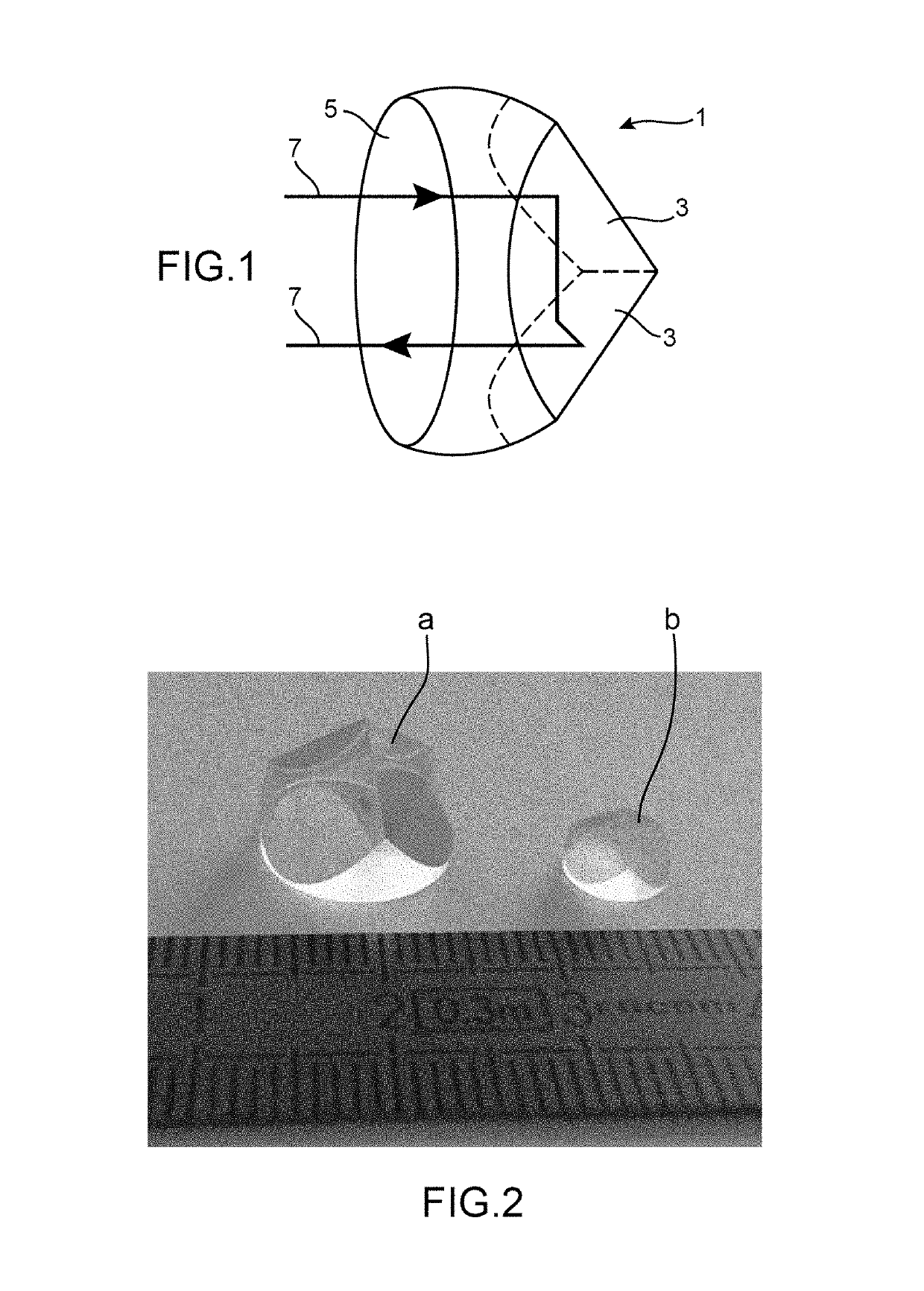
[0171]This example illustrates the preparation via a sol-gel route of a retroreflector according to the invention, this retroreflector having a cube corner shape or more specifically a shape comprising three perpendicular flat faces planes relatively to each other and curvilinear face connecting the apices of the perpendicular faces.

[0172]To do this, the preparation of the retroreflector occurs in three steps:[0173]a first step for preparing the mold (said to be below step a);[0174]a step for preparing the sol-gel solution (said to be below step b);[0175]a step for manufacturing the retroreflector as such (said to be below step c).

[0176]Finally, this example includes a portion relative to the characterization of the constitutive xerogel of the retroreflector (said below to be step d).

[0177]a) Step for Preparing the Mold

[0178]The model used for the manufacturing of the mold is illustrated by portion a) of FIG. 2, which appears as a shape comprising two flat faces perpendicular to eac...

example 2

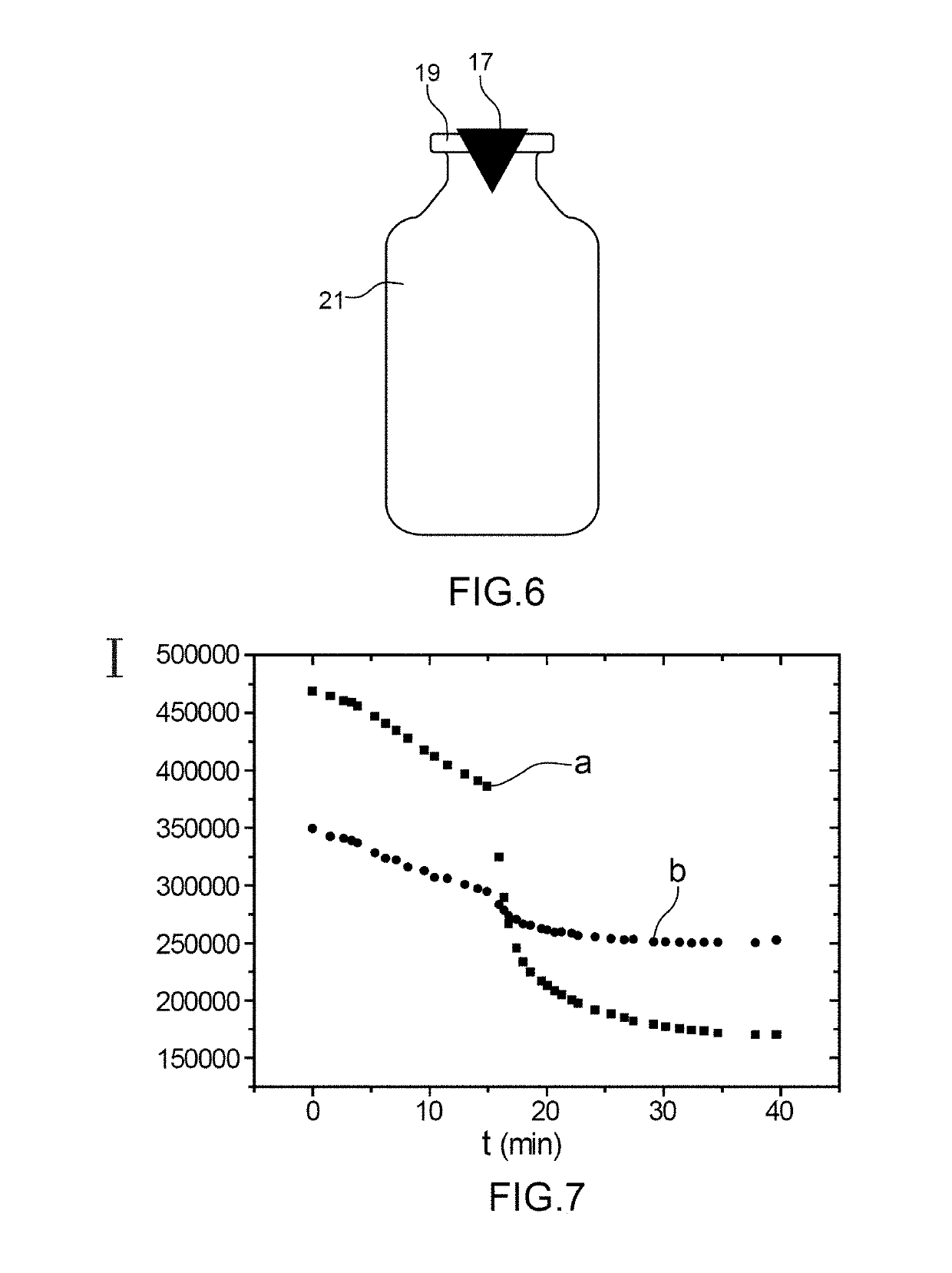
[0223]This example has the intention of demonstrating the efficiency of the retroreflector prepared in Example 1 for detecting a volatile organic compound (VOC), which is orthonitrophenol (this compound being obtained here from the supplier Sigma Aldrich), which fits the following formula:

[0224]

[0225]This compound may be emitted after hydrolysis of an enzymatic substrate with a specific enzyme of a microorganism. The detection of such a compound may have a certain interest for indirect detection of microorganisms, as illustrated by the article Phys. Chem. Chem. Phys, Vol. 15, no. 38, pages 15840-15844.

[0226]The retroreflector (reference 17) prepared in Example 1 is placed in a septum in rubber (reference 19), which hermetically closes a flask (reference 21) with a volume of 15 mL, as illustrated in FIG. 6.

[0227]To do this, the septum is pierced with a dye cutter, in order to obtain a hole with a diameter of 6 mm, which is intended to receive the retroreflector. Once placed on the fl...


PUM

PropertyMeasurementUnit
refractive indexaaaaaaaaaa
angleaaaaaaaaaa

Abstract

The invention relates to a retroreflector able to be placed in contact with an environment, comprising, by way of constituent material, a material enabling a parameter of said environment to be picked up, said material modifying the optical transmission properties of the retroreflector when said parameter is present, said retroreflector being able to receive an incident light beam via a first face and to reemit a light beam via said first face.

Description

CROSS-REFERENCE TO RELATED APPLICATIONS[0001]This application is a U.S. national phase under the provisions of 35 U.S.C. § 371 of International Patent Application No. PCT / EP15 / 80092 filed Dec. 16, 2015, which in turn claims priority of French Patent Application No. 1462627 filed Dec. 17, 2014. The disclosures of such international patent application and French priority patent application are hereby incorporated herein by reference in their respective entireties, for all purposes.TECHNICAL FIELD[0002]The present invention relates to a retroreflector made in a specific material, which retroreflector gives the possibility of both ensuring retroreflection functions and capture of an operating parameter as well as a method for detecting a parameter of the environment by means of said retroreflector.[0003]The invention thus finds application in the field of the measurement of environmental parameters, such as chemical composition, temperature or the presence of radiations, notably of ioni...

Claims


Application Information

Patent Timeline
Patent Type & Authority Patents(United States)
IPC IPC(8): G01N21/78G01N33/543G02F1/1335C12Q1/6837G02B5/122G02F1/21G01N21/80G01N21/77
CPCG01N21/78C12Q1/6837G01N21/783G01N33/54373G02B5/122G02F1/216G02F1/133553G01N2021/7796G01N21/80G01N2021/7759G01N2021/7773G01N2021/7783
Inventor MARCOUX, PIERREJOLY, PIERREVRIGNAUD, MARJORIEFATHALLAH, TAREK
Owner COMMISSARIAT A LENERGIE ATOMIQUE ET AUX ENERGIES ALTERNATIVES
Features
  • R&D
  • Intellectual Property
  • Life Sciences
  • Materials
  • Tech Scout
  • Unparalleled Data Quality
  • Higher Quality Content
  • 60% Fewer Hallucinations
Learn More