Energy recovery pulse forming network

a technology of energy recovery and pulse forming, which is applied in the direction of sustainable manufacturing/processing, final product manufacturing, transportation and packaging, etc., can solve the problems of large current demand, large current demand, and imposed practical limit on the velocity of the projectile, so as to reduce the amount of energy required

Active Publication Date: 2019-06-04
UNITED STATES OF AMERICA
View PDF8 Cites 2 Cited by
  • Summary
  • Abstract
  • Description
  • Claims
  • Application Information

AI Technical Summary

Benefits of technology

[0031]Embodiments in accordance with the invention include an energy recovery pulse forming network and method that recover at least a portion of the energy in a railgun by transferring energy dissipated from the railgun inductance back to an initial source of the energy, such as an input capacitor, for use by the powering circuit. This in turn reduces the amount of energy required from a power source to charge the input capacitor during subsequent railgun firings.

Problems solved by technology

The initial flow of current through the rails and armature runs through the interface between the rails and the aluminum armature, which results in heating at the contact and the melting of the aluminum.
This need to melt the aluminum armature at the start of a shot means that a large current is demanded early, even before the armature can begin to move effectively.
One current limitation is the practical limit to the velocity of the projectile imposed by the atmosphere.
In some systems, even with aerodynamic design of the projectile, this heating and energy loss becomes excessive once the projectile exceeds speeds of 2500 m / s.
Another limitation is imposed by the guidance of the projectile.
This means that the projectile cannot be spin stabilized as it moves through the rails.
Without spin stabilization, the delivery of the projectile will be highly inaccurate.
Unfortunately, these guidance systems have a limit on how rapidly they can change acceleration (known as jerk) and on how quickly they can accelerate.
This cannot be provided by some current standard power supplies on ships on an instantaneous basis, so an energy storage system is required.
Therefore, the proposed rate of fire will not be able to be maintained for a long time and will be based on the amount of energy storage provided to support the railgun system.

Method used


Image

  • Energy recovery pulse forming network
  • Energy recovery pulse forming network
  • Energy recovery pulse forming network

Examples


Embodiment Construction

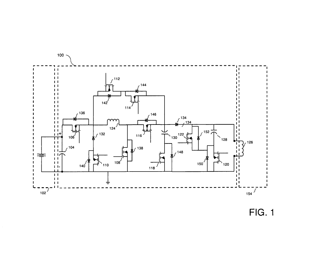
[0055]FIG. 1 illustrates an energy recovery pulse forming network 100 conductively coupled with a power supply 102 and a railgun 154 in accordance with one embodiment of the invention. In one embodiment, energy recovery pulse forming network 100 is implemented with railgun 154 to serve a load of railgun 154 and to return at least some of the energy stored in the magnetic field in the rails of railgun 154 back to the input capacitor(s) for reuse during the next transient of railgun 154.

[0056]In one embodiment, railgun 154 includes a pair of parallel conductive rails electrically coupled with energy recovery pulse forming network 100, herein also termed network 100. Network 100 is further electrically coupled with and powered by electrical power supply 102, such as a high voltage DC power supply. When a conductive armature is inserted between the rails, network 100 is completed. In one embodiment, the armature is a sliding armature used to launch a projectile out a muzzle end of railg...


PUM


Abstract

An energy recovery pulse forming network and method that recovers at least a portion of the energy in a railgun by transferring energy dissipated from the railgun inductance back to an initial source of the energy, such as an input capacitor, for use by the network. This reduces the amount of energy required from an external power source to charge the input capacitor during subsequent railgun firings.

Description

CROSS-REFERENCE TO RELATED APPLICATIONS[0001]This application claims the benefit of U.S. Provisional Application No. 62 / 452,827, filed Jan. 31, 2017, which is hereby incorporated in its entirety by reference.BACKGROUND OF THE INVENTION1. Field of the Invention[0002]The present invention relates generally to pulse forming networks. More particularly, the present invention relates to electrical circuits used in electromagnetic launchers, such as railguns.2. Description of the Related Art[0003]Electromagnetic launchers, such as railguns, require extremely high power and energy for each current pulse delivered by a power supply in order to support the firing of the load. The basic physical phenomenon that drives a railgun is the Lorentz force. In a railgun electrical current supplied by the power source, such as a pulse forming network (PFN), is conducted through two metal rails electrically coupled by a conductive armature, such as a conductive projectile, across the rails. The current...

Claims


Application Information

Patent Timeline
Patent Type & Authority Patents(United States)
IPC IPC(8): F41B6/00H02J7/00H02J7/34
CPCH02J7/007H02J7/0068F41B6/006H02J7/345H01L29/0634H01L29/8611H01L29/1608H01L29/6606Y02P70/50H01L21/0475H01L21/046
Inventor MARTINO, CHRISTOPHER ADRIAN
Owner UNITED STATES OF AMERICA
Why Eureka
Try Eureka