Supercharge Your Innovation With Domain-Expert AI Agents!

Image stabilization apparatus and image stabilization method

a technology of image stabilization and image processing, which is applied in the field of image stabilization apparatus and image stabilization method, can solve the problems of not being able to sufficiently raise the performance of image stabilization, and not being able to apply a complete integral in integration, so as to achieve the effect of increasing the correction effect of image stabilization processing

Active Publication Date: 2019-06-04
CANON KK
View PDF10 Cites 6 Cited by
  • Summary
  • Abstract
  • Description
  • Claims
  • Application Information

AI Technical Summary

Benefits of technology

The present invention improves image stabilization processing that uses an angular velocity sensor. This results in a more accurate and reliable correction effect.

Problems solved by technology

However, in image stabilization apparatuses that use an angular velocity sensor, it was not possible to sufficiently raise the performance of image stabilization due to the following two reasons.
The first is offset calculation error in the angular velocity sensor.
Because an angular velocity sensor includes sensor specific offset noise and low frequency band noise due to temperature fluctuation, it is not possible to apply a complete integral in integration processing at a time of calculating an image stabilization value.
Various adjustments are made on the image capturing apparatus at the time of shipment in order to reduce sensitivity variation, but an 100% image stabilization effect cannot necessarily be achieved since an adjustment error component necessarily remains.
Also, costs increase due to incorporation of an acceleration sensor in the case where an image stabilization effect at a time of macro imaging is improved by using an acceleration sensor.
Meanwhile, in cases where the acceleration on the image capturing apparatus is predicted from the drive amount and the position signal of the image stabilization apparatus, there is a problem in that estimation accuracy is bad if the shake is a minute shake.
Though it depends on the design of the feedback gain of the feedback control, the problem that deterioration of anti-shake performance remains when the feedback gain is made to be larger, even though convergence of the prediction is faster.
Also, when the feedback gain is made to be smaller, though the extent of the deterioration of anti-shake performance during prediction becomes smaller, the speed of convergence becomes slower.
For this reason, there are cases in which an error in the calculation result remains, and sufficient panning shot determination precision and assistance precision have not been achieved.

Method used


Image

  • Image stabilization apparatus and image stabilization method
  • Image stabilization apparatus and image stabilization method
  • Image stabilization apparatus and image stabilization method

Examples


first embodiment

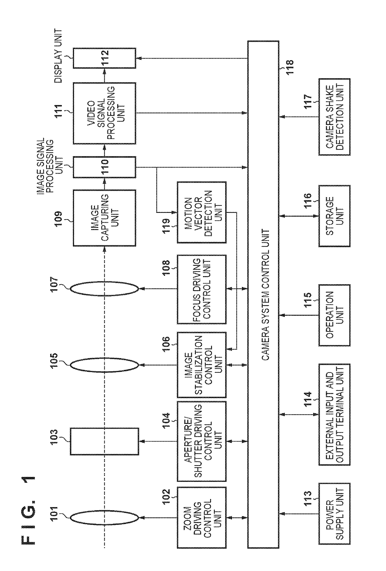
[0036]FIG. 1 is a block diagram illustrating a functional configuration of an image capturing apparatus including an image stabilization apparatus according to a first embodiment of the present invention, which here is a digital camera for imaging still images and moving images.

[0037]In FIG. 1, an optical system is configured to include a zoom unit 101 that includes a zoom lens for magnification / reduction, an aperture / shutter unit 103, an image stabilization unit 105, and a focus unit 107 that includes a lens for adjusting focus. For the zoom unit 101, drive control is performed by a zoom driving control unit 102, and for the aperture / shutter unit 103, drive control is performed by an aperture / shutter driving control unit 104. Also, for the image stabilization unit 105, drive control is performed by an image stabilization control unit 106, and for the focus unit 107, drive control is performed by a focus driving control unit 108.

[0038]An image capturing unit 109 performs photoelectr...

second embodiment

[0108]Next, a second embodiment of the present invention is described. In the foregoing first embodiment, a case in which a position of the correction lens of the image stabilization unit 105 can be detected by the position detection unit 212 is described, but in the second embodiment, a case in which the position detection unit 212 does not exist, and image stabilization is performed by open control is described. Note that the configuration of the image capturing apparatus in the second embodiment is similar to that which was described with reference to FIG. 1 in the first embodiment, and description is omitted.

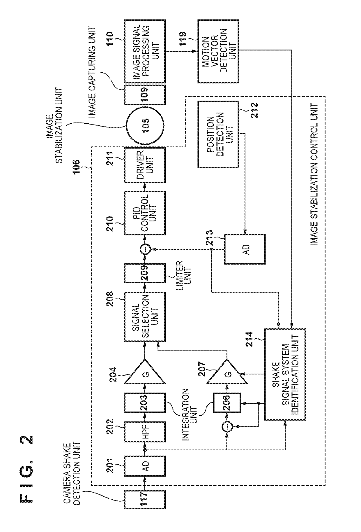
[0109]FIG. 8 is a block diagram illustrating a configuration of the image stabilization control unit 106 in the case of open control according to the second embodiment. Note that for similar configurations to the configurations described in the first embodiment with reference to FIG. 2, the same reference numerals are given, and description is omitted as appropriate.

[0110]Be...

third embodiment

[0119]Next, a third embodiment of the present invention is described. In the third embodiment, a panning shot assistance function for capturing while tracking a moving subject is described.

[0120]Typically, a setting of a shutter speed Tv for making a background flow by in a panning shot is set to be slow, but the slower it is made to be, the more a shift between a movement of an actual subject and a panning speed of the image capturing apparatus will remain as a blur of the subject. Accordingly, a function that causes a blur of a subject to be cancelled by driving an image stabilization unit at a speed that is the difference between the actual movement speed of subject and the speed of the image capturing apparatus is a panning shot assistance function.

[0121]For this, it is necessary to detect the speed of the subject using a motion vector. For the motion vector, a local motion vector is generated for each small block in a screen, and for each individual local motion vector, a backg...


PUM


Abstract

An image stabilization apparatus comprises: an identification unit that, based on an angular velocity signal outputted from a shake detection unit, a motion vector calculated from a difference between frames of images outputted from an image sensor, and a position signal indicating a position of a correction unit that corrects a shake optically, identifies an output variation of the shake detection unit; and a conversion unit that converts the angular velocity signal into a shake correction amount by correcting the angular velocity signal based on the output variation identified by the identification unit.

Description

BACKGROUND OF THE INVENTION[0001]Field of the Invention[0002]The present invention relates to an image stabilization apparatus and an image stabilization method.[0003]Description of the Related Art[0004]Interchangeable lenses and image capturing apparatuses comprising an image stabilization apparatus that detects a camera shake and moves a lens or an image sensor that can move to correct an image shake due to the detected camera shake are known. An image stabilization function of such a method is known as optical image stabilization. Also, in recent years, there are image stabilization functions that, for a moving image, output by extracting a frame image whose position is shifted in a direction that cancels a camera shake, and this is used in small-scale / light weight image capturing apparatuses, and mobile telephones with image capturing apparatuses. Image stabilization of such a method is known as electrical image stabilization.[0005]As a method of detecting a shake, an angular ve...

Claims


Application Information

Patent Timeline
Patent Type & Authority Patents(United States)
IPC IPC(8): H04N5/232H03H17/02H03H17/04
CPCH04N5/23287H03H17/0211H03H17/04H04N5/23258H04N5/23254G03B2217/005G03B2205/0007G03B5/00H04N23/6815H04N23/682H04N23/6812H04N23/687H04N23/6811
Inventor MIYAHARA, SHIMPEI
Owner CANON KK
Features
  • R&D
  • Intellectual Property
  • Life Sciences
  • Materials
  • Tech Scout
  • Unparalleled Data Quality
  • Higher Quality Content
  • 60% Fewer Hallucinations
Learn More