Method, computer program and system for optimizing radiotherapy treatment

a radiotherapy treatment and optimization technology, applied in radiation therapy, x-ray/gamma-ray/particle irradiation therapy, therapy, etc., can solve the problems that the solution developed for photon based radiotherapy cannot be easily applied to ion based radiotherapy, computation may become very difficult, and it is practically impossible to create an optimal plan manually

Active Publication Date: 2019-06-11
RAYSEARCH LAB
View PDF7 Cites 17 Cited by
  • Summary
  • Abstract
  • Description
  • Claims
  • Application Information

AI Technical Summary

Benefits of technology

[0019]This enables automatic optimization of the passive devices, reducing the amount of manual editing needed to create the treatment plan. Thus, according to the invention, the quality of a treatment plan could be improved compared to prior art methods, especially for complex cases, and high quality treatment plans can be determined also for cases that are too complex to handle manually. Also, a treatment plan can be created in less time than with the prior art methods.
[0021]Another advantage is the possibility to take uncertainties (e.g. in beam range and patient setup) into account. Since the method according to the invention is based on optimization algorithms, rather than forward planning, it is possible to use robust optimization. This makes it possible to take into account uncertainties for example in the patient's exact position or the beam range

Problems solved by technology

One of the main challenges therefore is to design the block and the compensator to shape and modulate the ion beam, so that it will travel the exact distance to the remote end of the tumour along a given beam passing through the tumour.
Solutions developed for photon based radiotherapy cannot be easily applied to ion based radiotherapy.
For complex patient geometries and tumour shapes, the computation may become very difficult.
Some cases may be so complex that it may be practically impossible to create an optimal plan manually.
In such cases, it is difficult to achieve a uniform dose distribution at the border areas between the ion beams.
It will for example not handle cases where the uniformity is different in different parts of the patch region.
Furthermore it is not a general method to design the beam energy, range modulator, block and compensator for any beam design.

Method used


Image

  • Method, computer program and system for optimizing radiotherapy treatment
  • Method, computer program and system for optimizing radiotherapy treatment

Examples


Embodiment Construction

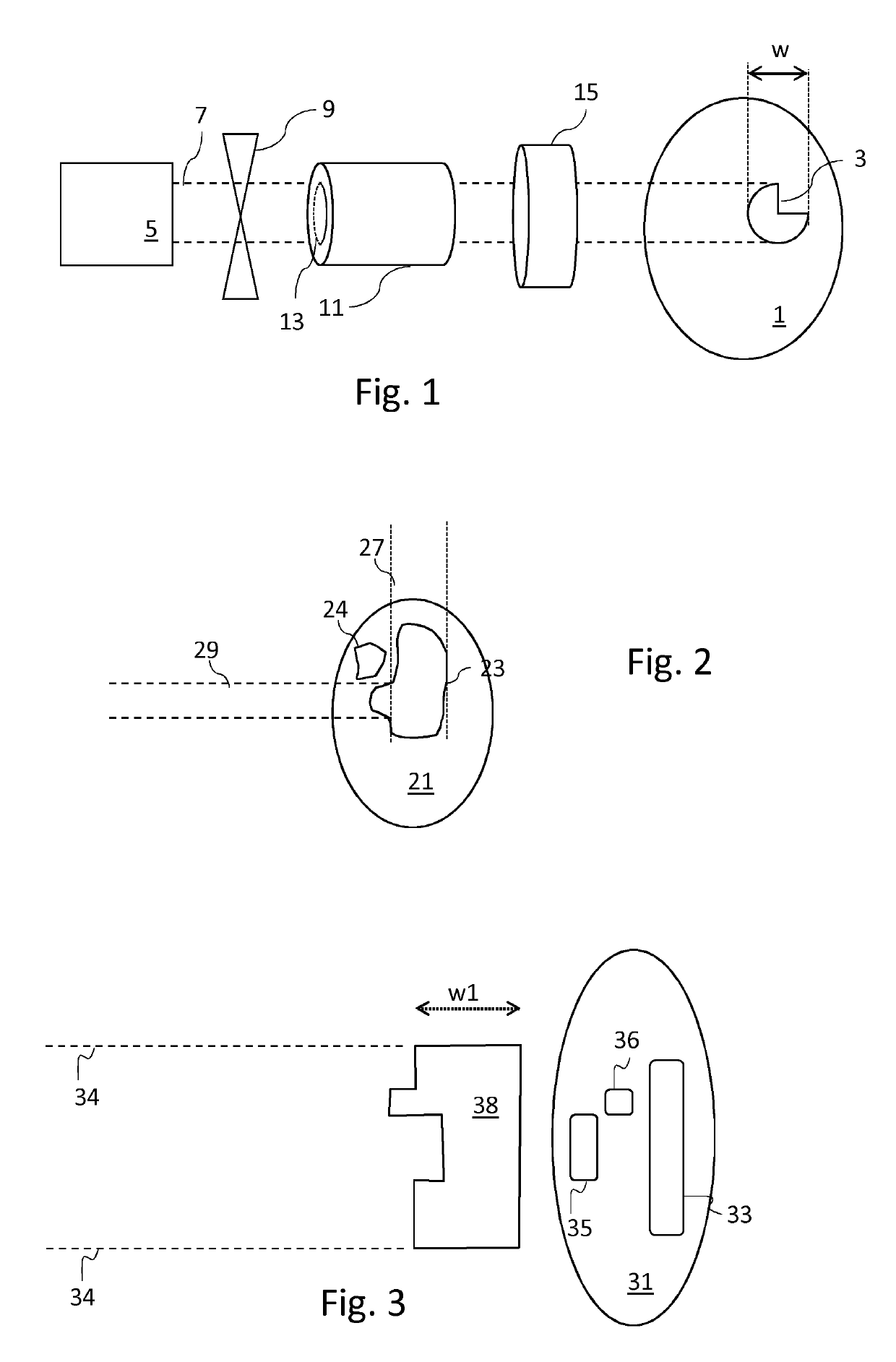
[0038]FIG. 1 shows schematically an example of a system for passive ion therapy in which the invention may be implemented. A patient 1 that is to be subjected to ion therapy is shown schematically to the right in FIG. 1. A region of interest ROI, or target 3, within the patient 1 represents the organ or other tissue that is to receive the radiotherapy. The maximum width of the target 3 is marked as w. As is common in the art, there may also be defined critical areas within the patient, which are areas in which it is particularly important to avoid radiation, although this is not shown in FIG. 1.

[0039]A radiation source 5 provides an ion beam 7 having a sufficient energy to achieve the desired maximum range, typically reaching to the distal target 3 edge. Typically one or two scattering devices (not shown) is arranged to create a broad field of radiation. Alternatively a uniform scanning technique or wobbling may be used to create a broad field. In pencil beam scanning technique, whe...


PUM


Abstract

An optimization method for ion based radiotherapy includes inverse planning based on optimization variables related to the particle energy, a range modulator or ridge filter, a block and / or a range compensator. This enables automatic optimization of complex cases.

Description

[0001]This application is the National Stage of International Application No. PCT / EP2016 / 064551, filed June 23, 2016, and claims benefit of European Patent Application No. 15173971.1 filed June 25, 2015.TECHNICAL FIELD[0002]The present invention relates to radiation therapy planning, and in particular to optimization of ion therapy in which a tumour is targeted with a beam of ions (e.g. protons or heavier ions like carbon).BACKGROUND AND RELATED ART[0003]Radiotherapy is commonly used for treating diseases such as cancer. Various types of radiation sources may be used. The predominant type of radiation used today is photon radiation. Although more expensive than photon radiotherapy, ion based therapy methods, such as proton and carbon therapy, are becoming more common because of their advantages. While photons will pass through a patient's body and emit energy along the whole path, ion beams are subject to very little lateral scattering and can be made to stop at a desired depth in t...

Claims


Application Information

Patent Timeline
Patent Type & Authority Patents(United States)
IPC IPC(8): A61N5/10
CPCA61N5/1031A61N2005/1096A61N2005/1095A61N2005/1087
Inventor GLIMELIUS, LARSERSMARK, TOREJANSON, MARTIN
Owner RAYSEARCH LAB
Why Eureka
Try Eureka