Laser processing apparatus

a technology of processing apparatus and laser, which is applied in the direction of metal-working apparatus, welding apparatus, manufacturing tools, etc., can solve the problems of lowering the suctioning capability of the suction mechanism, insufficient suction of debris, and incomplete processing of plate-shaped workpieces, so as to prevent the suctioning capability of the suction means from being lowered

Active Publication Date: 2019-06-11
DISCO CORP
View PDF23 Cites 1 Cited by
  • Summary
  • Abstract
  • Description
  • Claims
  • Application Information

AI Technical Summary

Benefits of technology

[0004]It is therefore an object of the present invention to provide a laser processing apparatus which suctions debris sufficiently and whose suctioning capability will not be lowered.
[0007]With the laser processing apparatus according to the present invention, the suction means suctions debris on the protective film sufficiently, and the suctioned debris is prevented from remaining in the debris trapping chamber, so that the suctioning capability of the suction means is prevented from being lowered.
[0008]Inasmuch as the suction means includes the cleaning air ejection port for ejecting air across the laser beam passage port toward the suction port to clean the laser beam passage port, the optical path of the laser beam is prevented from being clogged off when the plate-shaped workpiece is laser-processed.

Problems solved by technology

Therefore, the suction mechanism suctions the debris and also the fused protective film, and the fused protective film is liable to lower the suctioning capability of the suction mechanism to the extent that it fails to suction the debris sufficiently.
Due to the insufficient suctioning of the debris, debris tends to be left on the protective film and block the laser beam, making the processing of the plate-shaped workpiece incomplete.
The insufficient suctioning of the debris also causes debris to gather in the optical path of the laser beam in a manner to block the laser beam, resulting in incomplete processing of the plate-shaped workpiece.

Method used


Image

  • Laser processing apparatus
  • Laser processing apparatus
  • Laser processing apparatus

Examples


Embodiment Construction

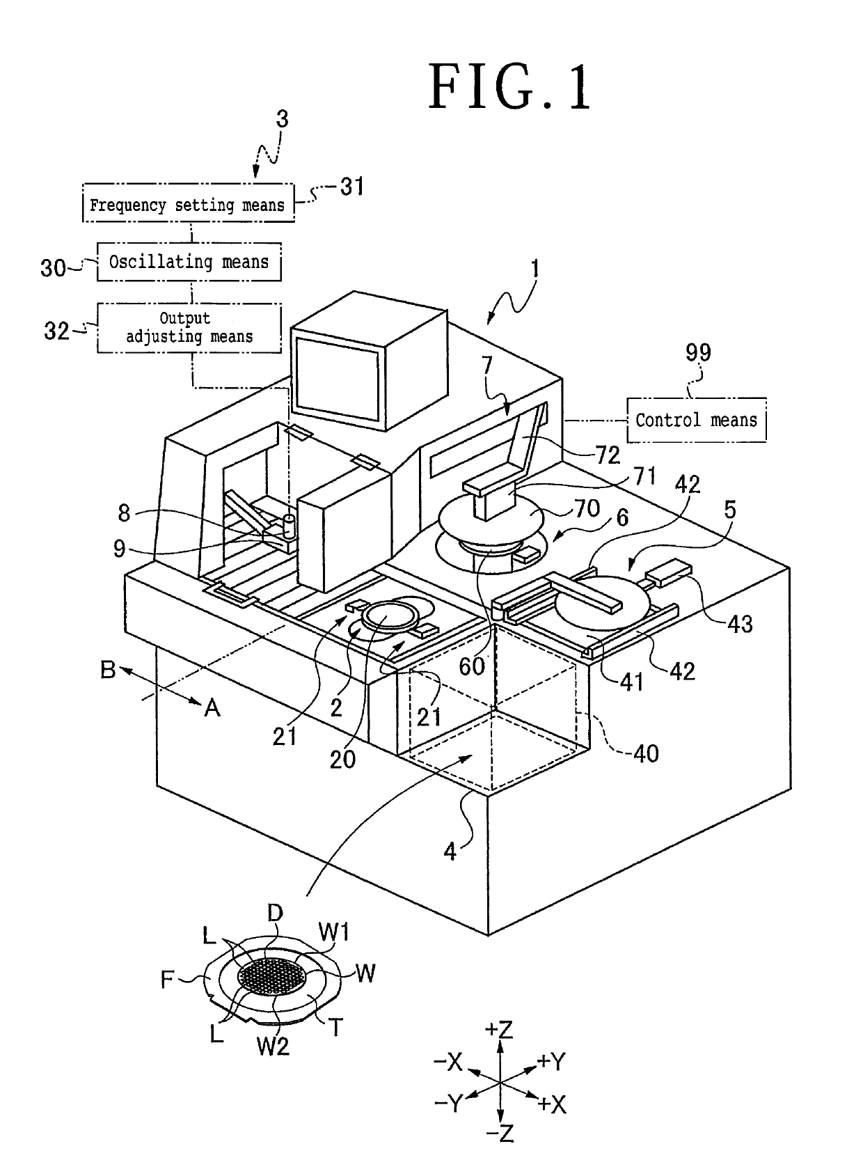
[0014]As shown in FIG. 1, a laser processing apparatus 1 according to an embodiment of the present invention is an apparatus configured to process a plate-shaped workpiece W held on a chuck table 2 by using laser processing means 3. The plate-shaped workpiece W has a reverse side W2 applied to a tape T to which a ring-like frame F is applied. The plate-shaped workpiece W is supported on the frame F by the tape T. The plate-shaped workpiece W has a face side W1 which is divided by a plurality of crossing projected dicing lines L into areas where a plurality of devices D are formed.

[0015]The laser processing apparatus 1 includes, in its front portion in the direction indicated by the arrow −Y, a cassette placement area 4 where a cassette 40 housing a plurality of plate-shaped workpieces W supported on respective frames F is placed. The cassette placement area 4 is vertically movable. A temporary placement area 41 for temporarily placing therein a plate-shaped workpiece W supported on ...


PUM

PropertyMeasurementUnit
wavelengthaaaaaaaaaa
areaaaaaaaaaaa
optical pathaaaaaaaaaa

Abstract

A laser processing apparatus has a suction unit for suctioning debris. The suction unit includes a debris trapping chamber and a cleaning unit for cleaning the inside of the debris trapping chamber. The cleaning unit includes a shutter for closing an opening of the debris trapping chamber and a cleaning water supply port for supplying cleaning water to the debris trapping chamber when the opening thereof is closed. The shutter closes the opening of the debris trapping chamber, the suction unit exerts a suction through the suction port, and cleaning water is supplied from the cleaning water supply port to the debris trapping chamber and suctioned through the suction port to clean the inside of the debris trapping chamber.

Description

BACKGROUND OF THE INVENTIONField of the Invention[0001]The present invention relates to a laser processing apparatus which has a function to suction debris produced by a laser processing process.Description of the Related Art[0002]When an ablation process is carried on a plate-shaped workpiece to form a processed groove in the surface thereof by applying a pulsed laser beam which has a wavelength absorbable by the plate-shaped workpiece, the plate-shaped workpiece tends to be fused, producing debris. In order to prevent the debris from being attached to the surface of the plate-shaped workpiece, it is customary to form a protective film on the surface of the plate-shaped workpiece, so that the debris will be deposited on the protective film and then removed together with the protective film after the plate-shaped workpiece has been processed. There has also been proposed an apparatus for reducing debris attached to the protective film on a dicing line with a suction mechanism for su...

Claims


Application Information

Patent Timeline
Patent Type & Authority Patents(United States)
IPC IPC(8): B23K26/142B23K26/00B23K26/55B23K26/361B23K26/18
CPCB23K26/361B23K26/142B23K26/1423B23K26/40
Inventor YOSHII, SHUNGO
Owner DISCO CORP
Why Eureka
Try Eureka