Electric power tool

a technology of electric power tools and power tools, applied in the field of tools, can solve the problems of large circumferential size of electric power tools, insufficient compactness, and insufficient compactness, and achieve the effects of simple, compact and lightweight structure, reliable positioning, and steady work condition

Inactive Publication Date: 2019-06-11
NINGBO HAILIAN ELECTRIC APPLIANCE
View PDF24 Cites 0 Cited by
  • Summary
  • Abstract
  • Description
  • Claims
  • Application Information

AI Technical Summary

Benefits of technology

[0003]The technical problem that this invention aims to solve is to overcome the deficiency existed in the current technology, and provide an electronic power tool with a simple and compact structure, energy efficiency, and long service life.

Problems solved by technology

Moreover, the space is needed to set up the pushrod.
As a result, the electric power tool would be large in circumferential size, complicated in structure, and not compact enough.
The structure would be quite complicated as the structure should be designed to fit the axial movement of the pushrod.
At the same time, when the cutter holder is rotating, the pushrod should also be rotating accordingly, which consumes considerable energy.
Consequently, the other end of the pushrod and the sliding base would be worn out because of the relative rotation, which would shorten the service life of the electronic power tool.

Method used


Image

  • Electric power tool
  • Electric power tool
  • Electric power tool

Examples


Embodiment Construction

[0021]Hereinafter, this invention will be further described in conjunction with the accompanying figures and embodiments:

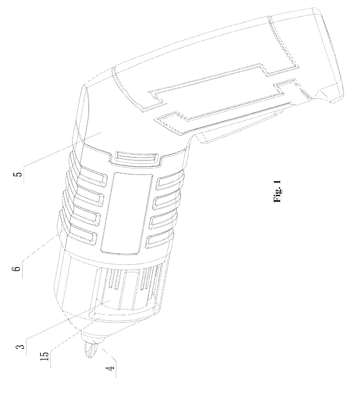
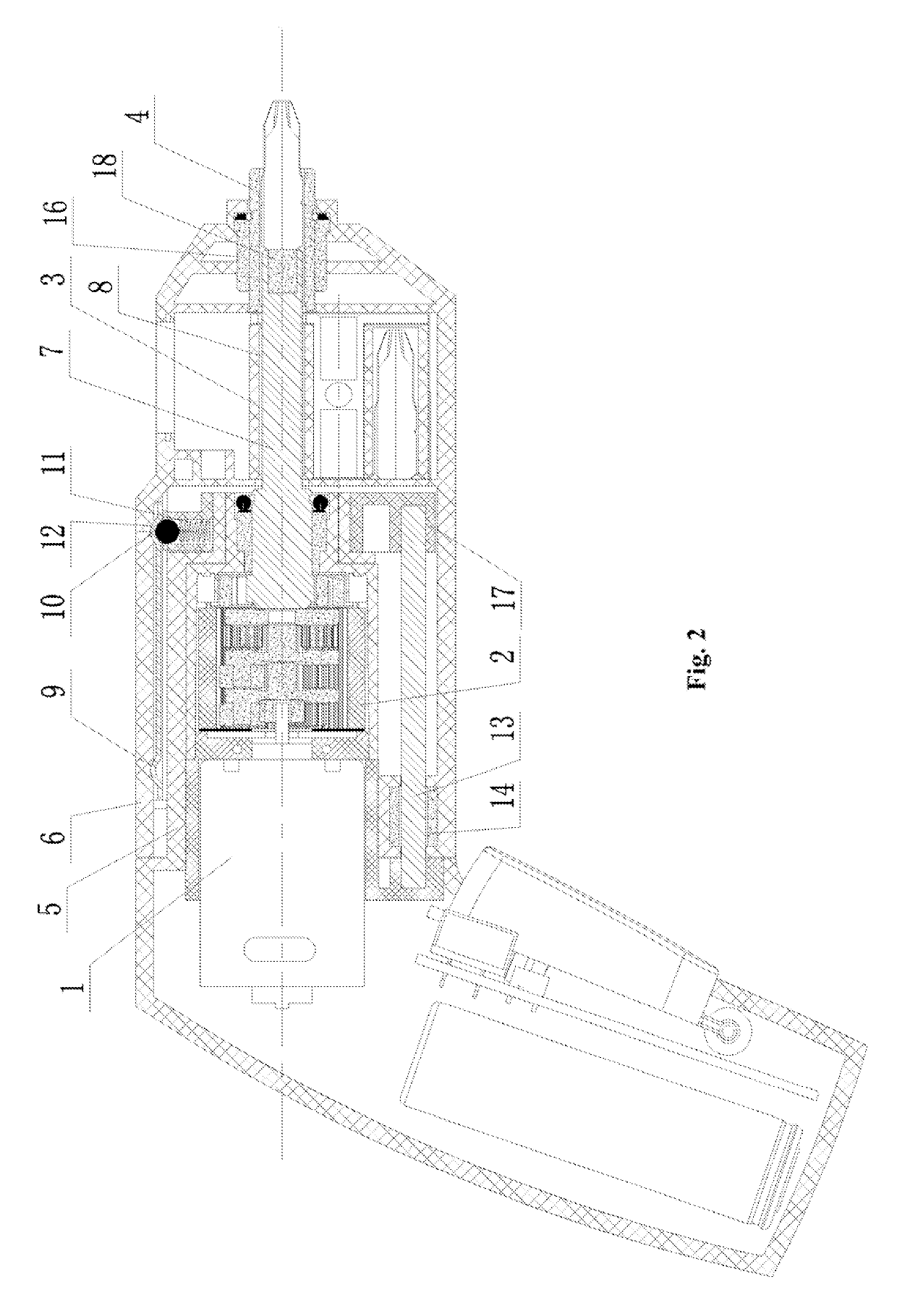
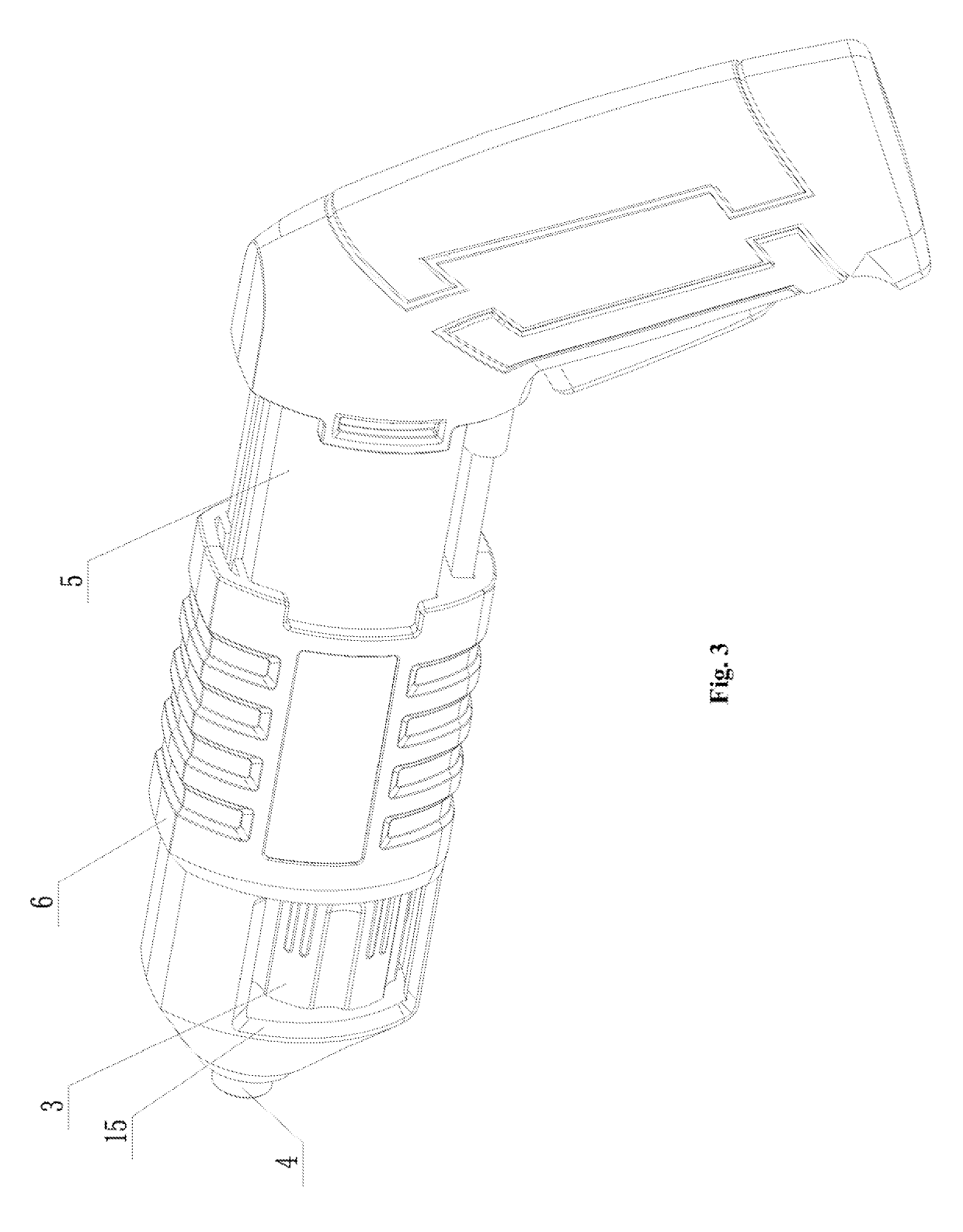
[0022]An electronic power tool includes: a motor 1, a gearbox 2, a cutter library 3 and a cutter holder 4; the motor 1 is connected with an input member of the gearbox 2; it further includes a first case 5 and a second case 6; motor 1 and gearbox 2 are disposed within the first case 5; the cutter library 3 and the cutter holder 4 are disposed within the second case 6; the cutter library 3 and the cutter holder 4 are both rotatably connected with the second case 6; the first case 5 and the second case 6 are capable of axially moving so that the output member 7 of gearbox 2 can be sequentially sleeved to a cutter hole 8 of the cutter library 3 and the cutter holder 4, or can be separated in the opposite direction. The sleeve connection between the output member 7 and the cutter holder 4 means that the output member is circumferentially sleeve-connected with the cutt...


PUM


Abstract

The present invention provides a structurally simple, compact, energy-saving electric power tool having a long service life, the tool including a motor, a gearbox, a cutter library and a cutter holder; the motor is connected with an input member of the gearbox; it further includes a first case and a second case; the motor and the gearbox are disposed within the first case; the cutter library and the cutter holder are disposed within the second case; the cutter library and the cutter holder are both rotatablely connected with the second case; the first case and the second case are axially movable so that an output member of the gearbox can be sequentially sleeved to a cutter hole 8 of the cutter library and the cutter holder, or can be separated in the opposite direction.

Description

TECHNICAL FIELD[0001]This invention relates to a tool, more specifically, to an electric power tool.BACKGROUND[0002]There is an electronic power tool currently existed in the market, which includes a motor, a gearbox, a pushrod for extending and retracting a cutter, a cutter library, a cutter holder; the motor is connected with an input member of the gearbox; an output member of the gearbox is connected with the pushrod; after an end of the pushrod entered the cutter holder, the pushrod drives the cutter holder to rotate; alternatively, the output member of the gearbox is connected with the cutter holder, and the output member drives the cutter holder to rotate. No matter which mechanism is chosen, in general, a first gear is set on the output member while a second gear is set on the pushrod or the cutter holder, and the fist gear engages with the second gear to reach the connection. Consequently, the output member is not coaxial with the cutter holder. Moreover, the space is needed...

Claims


Application Information

Patent Timeline
Patent Type & Authority Patents(United States)
IPC IPC(8): B25F5/02B25F5/00B25B21/00
CPCB25F5/029B25F5/001B25B21/00
Inventor HUANG, YONGLINHE, YUECUN
Owner NINGBO HAILIAN ELECTRIC APPLIANCE
Why Eureka
Try Eureka