Active force/vibration feedback control method and apparatus for a movable machine

a technology of active force/vibration feedback and control method, which is applied in the field of vehicular control, can solve the problem of other information having to be conveyed, and achieve the effect of efficient passing

Active Publication Date: 2019-06-11
BLUE LEAF I P INC
View PDF22 Cites 0 Cited by
  • Summary
  • Abstract
  • Description
  • Claims
  • Application Information

AI Technical Summary

Benefits of technology

[0017]An advantage of the present invention is that information is efficiently passed on to the machine operator by way of the control grasped by the operator.
[0018]Another advantage of the present invention is that in a noisy environment an alert can be quickly brought to the attention of the operator.

Problems solved by technology

A problem with the monolithic approach of the past is that other information has to be conveyed by way of another system or display rather than the operator control.

Method used


Image

  • Active force/vibration feedback control method and apparatus for a movable machine
  • Active force/vibration feedback control method and apparatus for a movable machine
  • Active force/vibration feedback control method and apparatus for a movable machine

Examples


Embodiment Construction

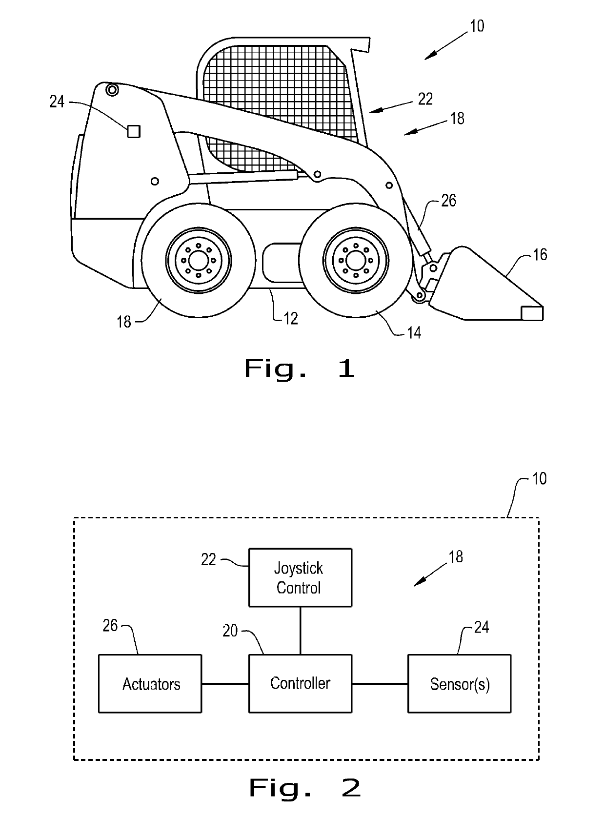
[0035]Referring now to the drawings, and more particularly to FIGS. 1 and 2 there is shown a movable machine 10 in the form of a vehicle 10 and more particularly in the form of a skid steer loader 10. The present invention is applicable to any vehicle and particularly to vehicles using controls that do not inherently have a reaction force directed back to the control that relates to a task undertaken by an operator of machine 10. Machine 10 includes a frame or chassis 12, a set of ground engaging devices, here illustrated as wheels 14, and a tool 16, here shown as a bucket 16. A control system 18 interfaces with parts of machine 10 that are not illustrated such as a transmission, an engine and other control systems. Control system 18 includes a controller 20, an operator control 22, sensors 24 and actuators 26. Controller 20 may be a stand-alone controller that communicates with other controllers used in machine 10, or the functions of controller 20 may be incorporated in another co...


PUM


Abstract

A movable machine including a chassis, a tool coupled to the chassis, an operator control carried by the chassis and a controller. The controller is communicatively coupled to the operator control. The controller being configured to send a force feedback and / or a vibration feedback to the operator control thereby conveying information to the operator. The information is not related to a load encountered by the tool.

Description

CROSS REFERENCE TO RELATED APPLICATION[0001]This application is the National Stage of International Application No. PCT / US2015 / 042790 filed Jul. 30, 2015, which claims priority to U.S. Provisional Patent Application No. 62 / 031,207 filed Jul. 31, 2014, the contents of which are incorporated herein by reference.BACKGROUND OF THE INVENTION[0002]1. Field of the Invention[0003]The present invention relates to vehicular controls and more specifically to a feedback regime for a vehicular control.[0004]2. Description of the Related Art[0005]Vehicles such as skid steer loaders are a mainstay of agricultural and construction work. In their most common configuration, they have two drive wheels on each side of a chassis that are driven in rotation by one or more hydraulic motors coupled to the wheels on one side and another one or more hydraulic motors coupled to the wheels on the other side.[0006]The wheels on one side of the vehicle can be driven independently of the wheels on the other side ...

Claims


Application Information

Patent Timeline
Patent Type & Authority Patents(United States)
IPC IPC(8): E02F9/20A01B71/02G05G5/03G05B11/01E02F9/24E02F3/34B60W50/16
CPCE02F9/2004A01B71/02B60W50/16E02F9/24G05B11/01G05G5/03E02F3/3414G05B2219/37396B60K26/021B60K2026/029
Inventor KASSEN, GARY R.WU, DUQIANGSINGH, ADITYAMELCHINGER, ULIGULATI, NAVNEETDEAN, PATRICK T.
Owner BLUE LEAF I P INC
Why Eureka
Try Eureka