

Gas-cooled welding gun for an arc welding device
a welding gun and arc welding technology, applied in the direction of cooled electrode holders, arc welding apparatus, electrode supporting devices, etc., can solve the problems of short circuit, endanger operating personnel, and difficulty in reliable heat dissipation
- Summary
- Abstract
- Description
- Claims
- Application Information
AI Technical Summary
Benefits of technology
Problems solved by technology
Method used
Image

Examples
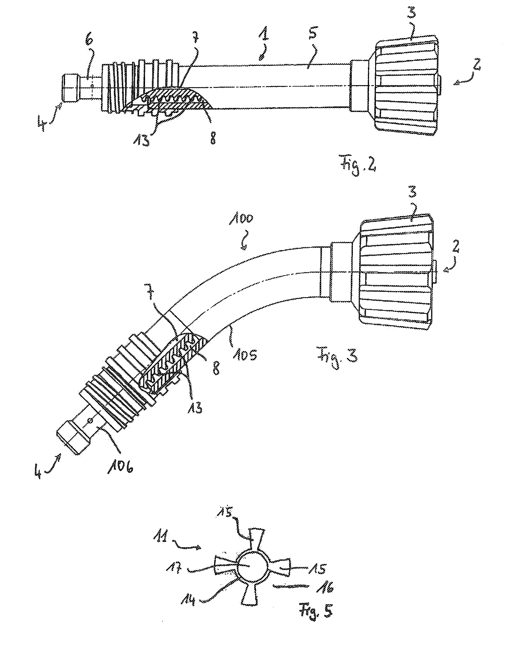
first embodiment
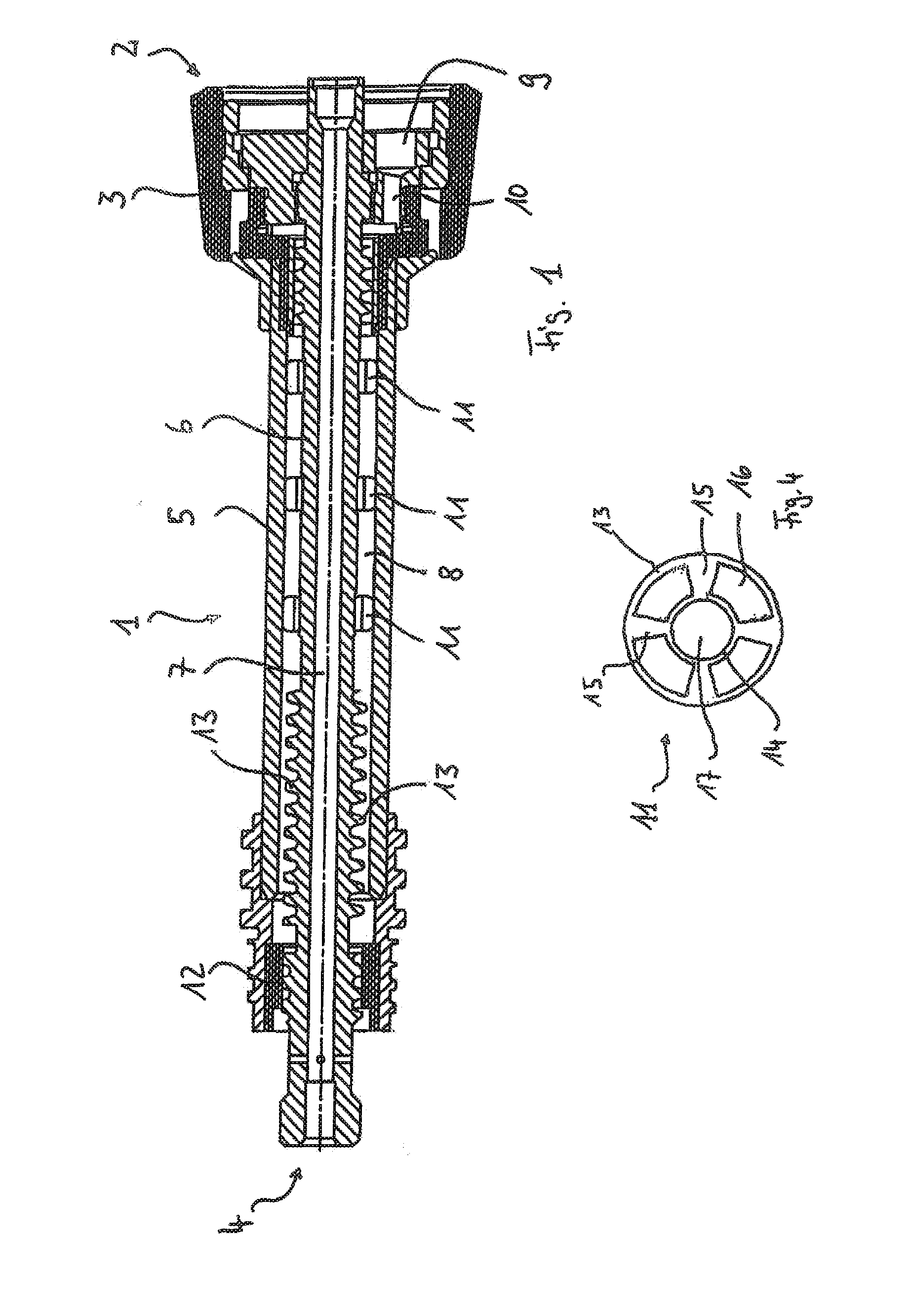
[0022]FIG. 4 a schematic top view of a possible spacer, and
second embodiment
[0023]FIG. 5 a schematic top view of a possible spacer.
METHODS(S) OF IMPLEMENTING THE INVENTION
[0024]The figures show schematic representations of embodiments of the invention. They do not reproduce all design details, nor are they necessarily to scale, but rather they are intended to be understood as schematic diagrams that illustrate essential features of the invention.
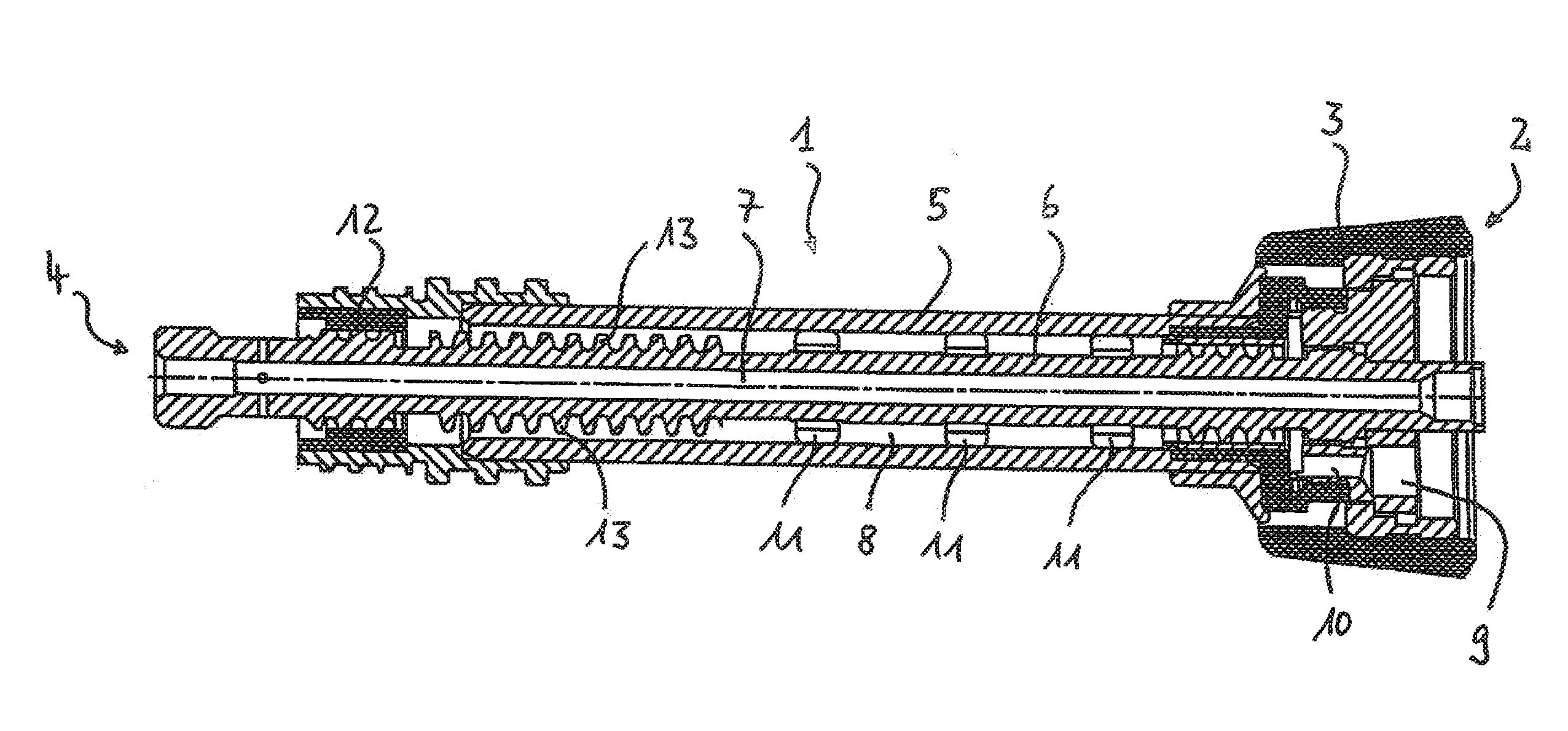
[0025]FIG. 1 shows a sectional side view of a welding gun representing essential components, and in general is referred to as 1. The welding gun 1 has a coupling nut 3 on a rearward connection end 2 for attachment to a corresponding connector on a media supply system, for example a so-called hose assembly. The welding end 4, which represents the front end of the welding gun 1, is on the side opposite the connection end 2.
[0026]The welding gun in FIG. 1 extends in a straight line between the connection end 3 and the welding end 4, and is externally bordered by an outer tube 5 in a corresponding middle section. A curr...
PUM
| Property | Measurement | Unit |
|---|---|---|
| electrically conductive | aaaaa | aaaaa |
| surface area | aaaaa | aaaaa |
| electrically insulating | aaaaa | aaaaa |
Abstract
Description
Claims
Application Information