Construction template with laser target device and method of use

a construction template and laser target technology, applied in the field of construction template systems, can solve the problems of added labor costs, added costs for the project, and poor rolling process, and achieve the effects of cost saving, easy design and planning, and convenient installation in the field

Inactive Publication Date: 2019-06-11
KELLER DAVID M
View PDF16 Cites 5 Cited by
  • Summary
  • Abstract
  • Description
  • Claims
  • Application Information

AI Technical Summary

Benefits of technology

[0009]The construction template system described herein provides an efficient way to locate one or more templates such that the installation process is more cost effective than existing systems. Additionally, by using strip templates that may be layered and / or sequenced the construction process is easier to design and plan for, as well as being easier to install in the field.
[0010]Some other advantages include aspects of the construction template system described herein such as having wall templates adhered to floor strip templates, and thus coordination issues that may otherwise arise between contractors are potentially avoided. Furthermore, templates may be all installed at the beginning of a project and thus are readily available to contractors of different trades during construction. Additionally, layering templates may help a construction team receive clear directions as a top layer(s) of a template stack are distorted or become damaged during construction. Finally, utilizing sequence marking on the templates may greatly reduce the number of target points required by the laser, which in turn may increase construction efficiency and simplify front end design efforts. Finally, printed templates described herein can sometimes print slightly off-scale and thus using the laser alignment of target points on the printed templates may serve as a double check on the accuracy of the overall construction template system.

Problems solved by technology

For example, the rolling process does not work well when one or more structures 115 rigidly attach to and extend from surface 105.
Further, the process 101 is time consuming, which results in added costs for labor.
In addition, the process 101 requires the use of a large amount of paper for each roll, which also results in added costs for the project.
Further, utilizing large rolls of templates requires expensive printing machines that are not portable, which results in added costs for the project.
Additionally, layering templates may help a construction team receive clear directions as a top layer(s) of a template stack are distorted or become damaged during construction.

Method used


Image

  • Construction template with laser target device and method of use
  • Construction template with laser target device and method of use
  • Construction template with laser target device and method of use

Examples


Embodiment Construction

[0024]Illustrative embodiments of the system and method of use of the present application are provided below. It will of course be appreciated that in the development of any actual embodiment, numerous implementation-specific decisions will be made to achieve the developer's specific goals, such as compliance with system-related and business-related constraints, which will vary from one implementation to another. Moreover, it will be appreciated that such a development effort might be complex and time-consuming, but would nevertheless be a routine undertaking for those of ordinary skill in the art having the benefit of this disclosure.

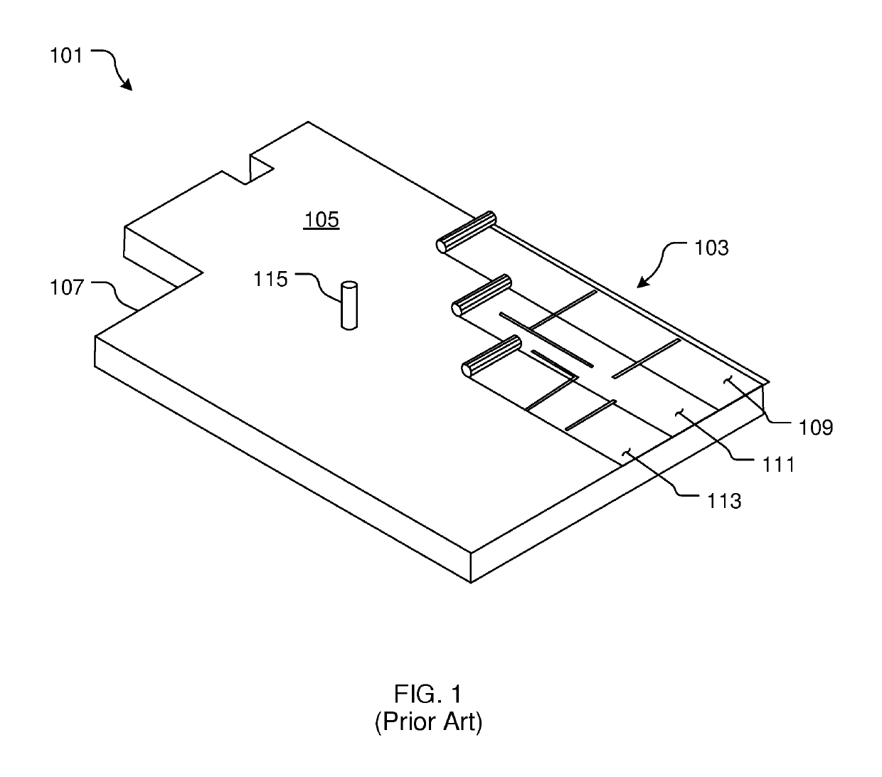
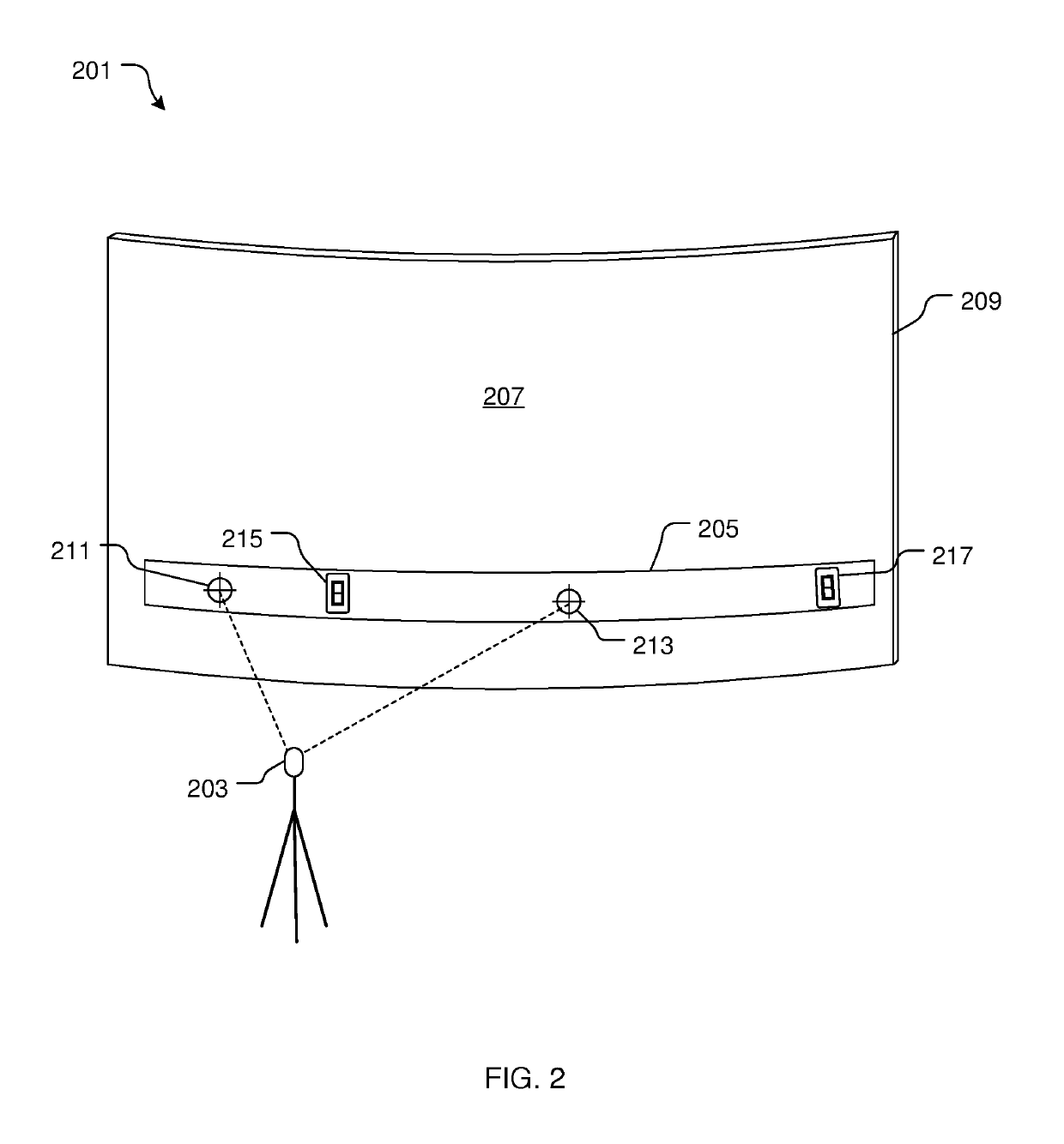
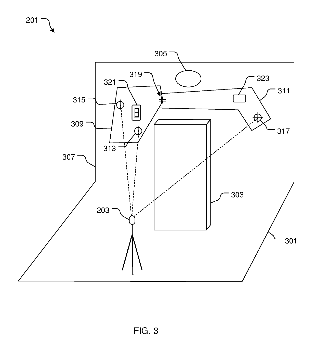
[0025]The system and method of use in accordance with the present application overcomes one or more of the above-discussed problems commonly associated with conventional construction template systems. Specifically, the features in the system of the present application are located with the assistance of parts of the construction accommodating the variab...


PUM


Abstract

Example systems and methods involving a construction template system are described. An example system includes a laser and a template. The laser is configured to indicate target points on a surface, such as a floor or wall of a building. Each of the target points is a predetermined location uploaded to the laser. The template includes target alignment points that correspond to the target points indicated by the laser. Furthermore, the template also includes a reference location. In examples, the reference location provides indicia of construction features as part of a building construction site. The template is adhered to the surface after aligning the target alignment points of the template with the corresponding target points.

Description

CROSS-REFERENCE TO RELATED APPLICATIONS[0001]The present application is a continuation-in-part of U.S. patent application Ser. No. 15 / 468,909, filed Mar. 24, 2017, which claims priority to U.S. Provisional Application No. 62 / 313,255, filed Mar. 25, 2016. The entire contents of U.S. patent application Ser. No. 15 / 468,909 and U.S. Provisional Application No. 62 / 313,255 are herein incorporated by reference into the present application.BACKGROUNDField[0002]The present application relates generally to construction template systems, and more specifically, to a template system for locating select features during construction.Description of Related Art[0003]Templates for residential and commercial building constructions are well known in the art and are effective means to map the location for the construction materials, e.g., an outlet, HVAC conduit, switches, and the like. In FIG. 1, a conventional process 101 includes adhering a plurality of templates 103 to a surface 105 of a building sl...

Claims


Application Information

Patent Timeline
Patent Type & Authority Patents(United States)
IPC IPC(8): G01B3/14G01B11/26E04G21/18
CPCG01B3/14G01B11/26E04G21/18E04F19/00G01C3/00G01B11/026G01C15/002G01C15/02G01S17/00
Inventor KELLER, DAVID M.
Owner KELLER DAVID M
Why Eureka
Try Eureka