
Power factor dimming

a technology of power factor and dimming, which is applied in the direction of lighting apparatus, electroluminescent light sources, light sources, etc., can solve the problems of negating dimming, adversely affecting the power factor, poor power factor of the system per definition, etc., and achieves the effect of reducing current and reducing power was

Inactive Publication Date: 2019-06-11
AZOTEQ HLDG LTD
View PDF21 Cites 1 Cited by
  • Summary
  • Abstract
  • Description
  • Claims
  • Application Information

AI Technical Summary

Benefits of technology

The patent text describes a new LED bulb or lamp that can work with older phase-cut dimmers to reduce power consumption. It is designed to maintain holding currents for leading edge dimmers and can also change its color temperature based on the level of current through the LEDs. The invention allows for a significant reduction in power factor and makes it easier to dim the LEDs without flickering. Overall, the patent text describes a solution to reduce energy consumption and make LED lamps more efficient.

Problems solved by technology

When a phase cut dimmer is used to effect dimming, the power factor is ignored by legislation and the power factor of the system becomes poor per definition because only a section of the AC cycle's power is used.
This will adversely affect the power factor and will in most cases negate dimming.
It is often mentioned to set the phase cut angle to zero, but this may not be practical in some systems and then this should only mean to introduce as little phase cutting as possible, and the phase cutting is not to limit the output power of the load, but rather for other considerations.

Method used


Image

  • Power factor dimming
  • Power factor dimming
  • Power factor dimming

Examples


Embodiment Construction

[0067]The following description of the appended drawings are presented merely to clarify the spirit and scope of the present invention, and not to limit it. It should be understood that these are exemplary embodiments, and a large number of alternative embodiments may exist which still fall within the scope of the claims for the present invention.

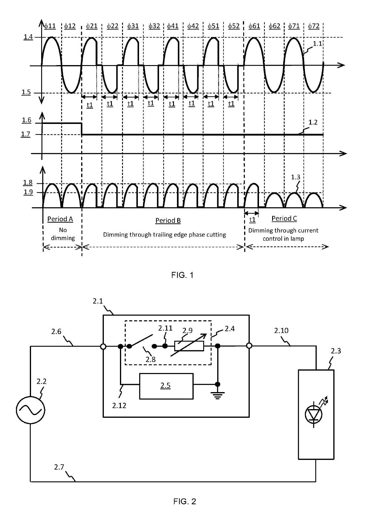
[0068]FIG. 1 presents exemplary waveforms for an embodiment of the invention which comprise an intelligent dimmer and an associated LED lamp, or another load, supplied by said dimmer, similar to what has been described earlier in the present disclosure. Waveform 1.1 is a qualitative representation of the voltage supplied by said dimmer to said lamp. Waveform 1.2 is a qualitative representation of the average power drawn by said lamp, and waveform 1.3 is a qualitative representation of the current through LED's in the lamp, or of current through another type of load. As is evident from FIG. 1, seven mains cycles are depicted, comprising firs...


PUM


Abstract

An intelligent mains power supply dimmer unit and LED lamp combination with improved power factor. The dimmer applies phase-cutting at a first angle for a first period to a mains voltage supplied to the lamp, whereafter the dimmer removes the phase-cutting. The lamp interprets the first angle as a first power level, which is then stored. The lamp retrieves the level after the first period and regulates its consumption accordingly.

Description

BACKGROUND OF THE INVENTIONObjectives[0001]1. Backwards compatibility of bulbs / lamps to existing phase cut dimmers.[0002]2. Use of new dimmer with old LED bulbs.[0003]3. Improving flicker and power factor of dimmed LED Lamps or other loads.[0004]A big user base of phase cut dimmers exists that won't be phased out soon. When a phase cut dimmer is used to effect dimming, the power factor is ignored by legislation and the power factor of the system becomes poor per definition because only a section of the AC cycle's power is used. In a business where power factor is factored into electricity usage costs, the dimming of lights through phase cut dimming has little or no effect on the cost of using the lamp. This means even if the lights are dimmed to 50% the cost of the electricity is the same as for 100%.[0005]Furthermore, in LED lamps the phase cut dimming has a direct 100% flicker effect unless significant capacitance is added to the lamp circuitry. This will adversely affect the powe...

Claims


Application Information

Patent Timeline
Patent Type & Authority Patents(United States)
IPC IPC(8): H05B37/00H05B33/08H05B39/00H05B44/00
CPCH05B33/0854H05B45/10
Inventor BRUWER
Owner AZOTEQ HLDG LTD
Learn More