
Power storage system

a technology of power storage and power supply, which is applied in the field of power storage system, can solve the problems of increased charging loss, reduced charging power supplied to the battery, prolonged charging time, etc., and achieves the effects of reducing charging time, increasing battery temperature, and increasing charging efficiency

Inactive Publication Date: 2019-06-18
TOYOTA JIDOSHA KK
View PDF12 Cites 4 Cited by
  • Summary
  • Abstract
  • Description
  • Claims
  • Application Information

AI Technical Summary

Benefits of technology

The patent text explains that when a heater consumes a lot of electric power, it can reduce the amount of power that can be used to charge a battery. This results in longer charging times and increased charging loss, even when a large amount of charging power is supplied to the battery. The technical effect of this patent is to improve the efficiency of battery charging by reducing the amount of power consumed by the heater.

Problems solved by technology

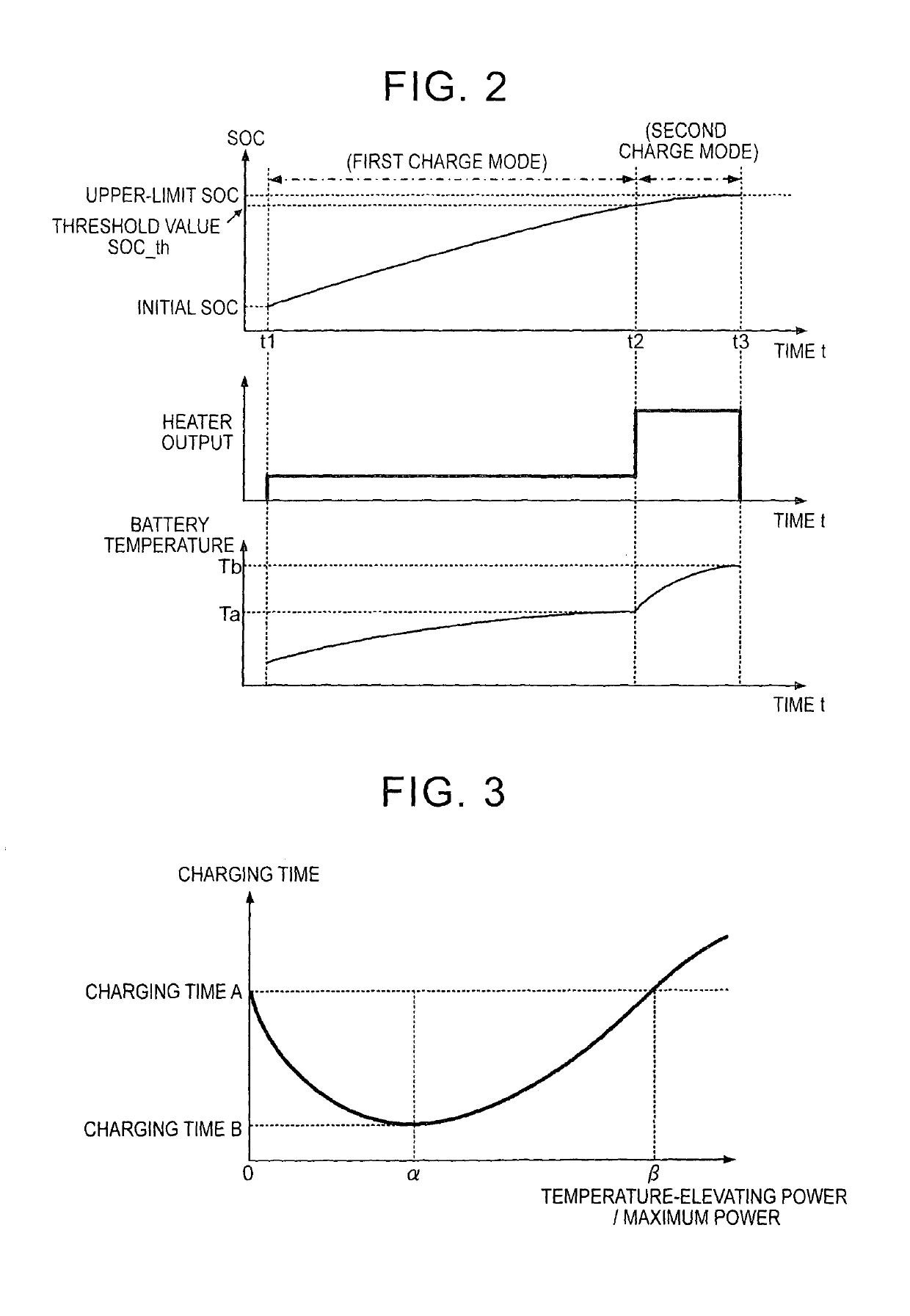
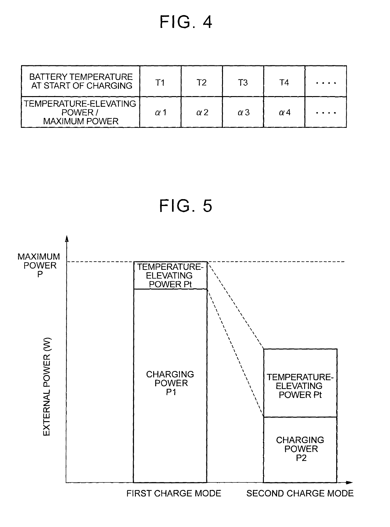
The electric power consumed by the heater cannot be used for charging the battery; therefore, when an excessively large amount of power (temperature-elevating power) is consumed by the heater, the charging power supplied to the battery is reduced, and the charging time is prolonged.
On the other hand, even when a large amount of charging power is supplied to the battery in a condition where the battery temperature is low, a charging loss is increased, and the charging time is prolonged, since the charging efficiency is low due to increase of the internal resistance.

Method used


Image

  • Power storage system
  • Power storage system
  • Power storage system

Examples


Embodiment Construction

[0028]One embodiment of the invention will be described.

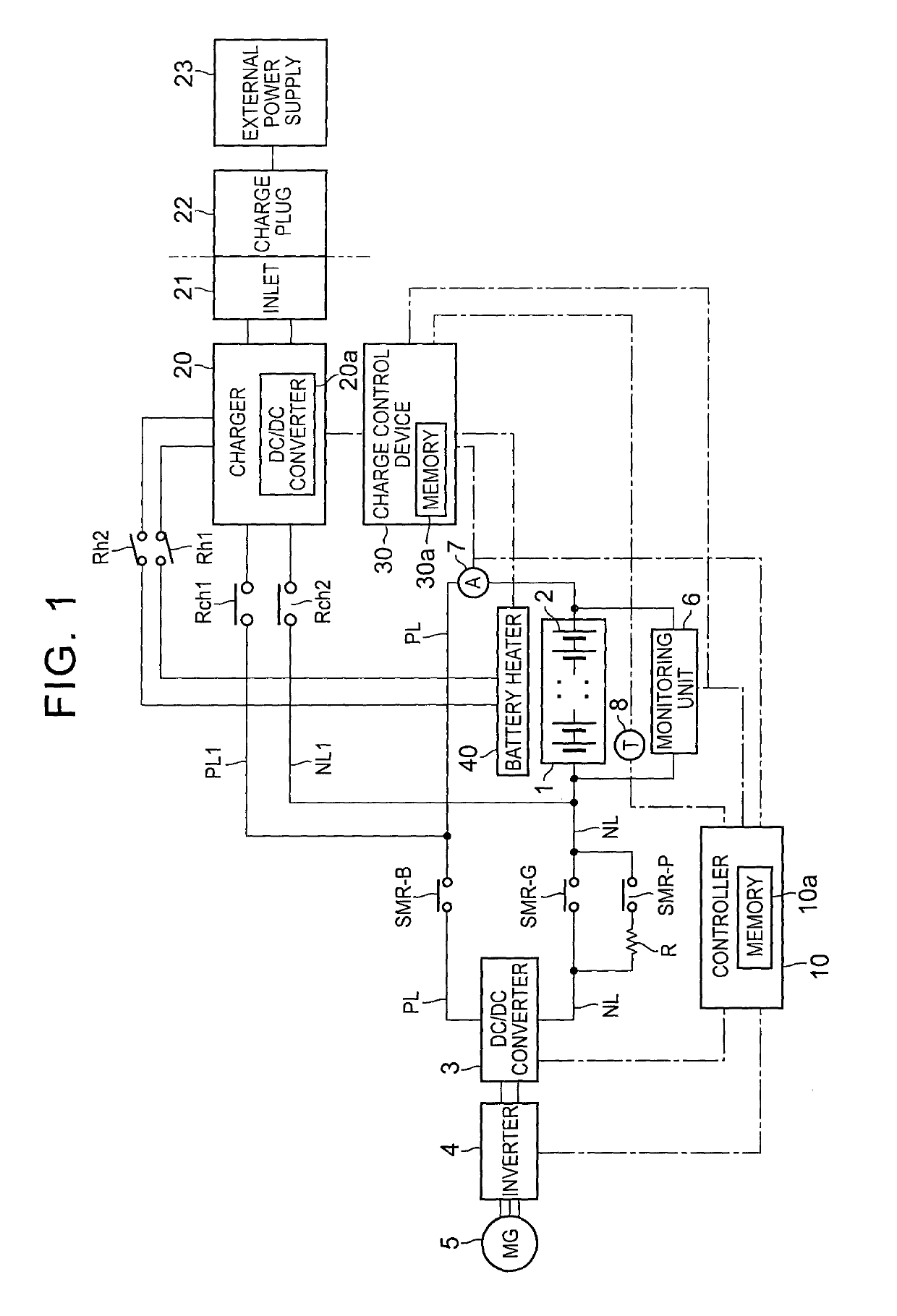
[0029]FIG. 1 through FIG. 8 show a first embodiment of the invention. FIG. 1 is a block diagram showing the configuration of a battery system installed on a vehicle of this embodiment. The battery system may be installed on a vehicle, such as a plug-in hybrid vehicle having a function of charging a battery with power from an external power supply, or an electric vehicle.

[0030]The battery system of this embodiment includes a charge / discharge system and an external charge system. In the charge / discharge system, DC power of a battery 1 is supplied to a motor-generator (MG) 5 via an inverter 4, and the battery 1 is charged with regenerative energy during braking of the vehicle. In the external charge system, a temperature regulator is provided for the battery 1, and the battery 1 is charged with electric power from an external power supply 23.

[0031]As shown in FIG. 1, the battery 1 is a battery assembly having a plurality of unit c...


PUM

PropertyMeasurementUnit
voltagesaaaaaaaaaa
voltagesaaaaaaaaaa
electric poweraaaaaaaaaa

Abstract

A power storage system for a vehicle includes a battery, a temperature sensor, a battery heater, a charger, and a controller. The battery is configured to supply electric power to a motor for traveling of the vehicle, and configured to be charged with external power supplied from an external power supply. The temperature sensor is configured to detect a temperature of the battery. The battery heater is configured to raise the temperature of the battery. The charger is configured to be connectable with the external power supply, and deliver the external power to the battery and the battery heater, respectively. The controller is configured to perform charge control. The charge control is a control that charges the battery with the external power. The controller is configured to store a map. The map specifies, for each temperature of the battery, a ratio of a temperature-elevating power supplied to the battery heater to a maximum power of the external power at the time when a charging time is minimized. The controller is configured to calculate the ratio, using the map, from the temperature of the battery measured at the time when charging is started. The controller is configured to perform temperature regulation control during charging, using the temperature-elevating power corresponding to the calculated ratio. The temperature regulation control is a control that supplies a part of the external power to the battery heater during charging so as to raise the temperature of the battery.

Description

BACKGROUND OF THE INVENTION1. Field of the Invention[0001]The invention relates to a power storage system for a vehicle, which includes a battery that supplies electric power to a motor for traveling of the vehicle and is chargeable with electric power supplied from an external power supply.2. Description of Related Art[0002]In a plug-in hybrid vehicle or an electric vehicle, a battery that supplies electric power to a motor for traveling of the vehicle can be charged (externally charged) with electric power supplied from an external power supply. It is generally known that the charging time is prolonged or increased as the temperature of the battery (battery temperature) is lowered. This is because, when the battery temperature is low, the internal resistance increases, and the charging efficiency deteriorates.[0003]In a system described in Japanese Patent Application Publication No. 2012-191783 (JP 2012-191783 A), when the battery is externally charged using a timer, a part of cha...

Claims


Application Information

Patent Timeline
Patent Type & Authority Patents(United States)
IPC IPC(8): B60L53/14B60L58/12B60L58/13B60L58/24B60L58/27B60L53/20H01M10/6571H01M10/625H01M10/633H01M10/48H01M10/615H01M10/44
CPCB60L53/14B60L53/20B60L58/12B60L58/13B60L58/24B60L58/27H01M10/443H01M10/486H01M10/615H01M10/625H01M10/633H01M10/6571B60L2210/10B60L2240/445B60L2240/545B60L2240/547B60L2240/549H01M2220/20Y02T10/705Y02T10/7005Y02T10/7044Y10S903/903H02J7/0021H01M10/63B60L53/00B60L50/53B60L58/15Y02T10/70Y02T10/7072Y02T90/14Y02E60/10
Inventor MURATA, TAKASHI
Owner TOYOTA JIDOSHA KK
Learn More