One-piece self-locking nut

a self-locking, one-piece technology, applied in the direction of threaded fasteners, fastening means, screws, etc., can solve the problems of requiring more material to implement, requiring more installation time, and requiring more material, so as to improve the installation speed, facilitate and reduce manufacturing costs, and facilitate the effect of assembly

Active Publication Date: 2019-06-18
CRUSHLOCK INC
View PDF28 Cites 5 Cited by
  • Summary
  • Abstract
  • Description
  • Claims
  • Application Information

AI Technical Summary

Benefits of technology

[0004]It is therefore a principal object of the present disclosure to provide a one-piece self-locking nut for permanent fastening on a bolt that can be readily fabricated with standard manufacturing methods and installed on a bolt with standard tools. It is a further object that the one-piece self-locking nut be easier and less expensive to manufacture, and lighter, stronger, and quicker to install than two-piece (or more) locking nuts.
[0006]When torqued down onto a fastener bolt, the one-piece, self-locking nut resembles a conventional nut in the locked position while forming a permanent lock, whereas the conventional nut is subject to loosening. The one-piece, self-locking nut can be fabricated by conventional nut manufacturing methods, and in use it threads on quickly like a conventional nut and installs with conventional tools. The self-locking nut installs faster and is lighter in weight without wasting added material as compared to two-piece locking nuts.

Problems solved by technology

However, the conventional use of locknuts requires added components to be used and manipulated with every permanent fastener, thereby taking up more time to install and more material to implement, and such locknuts may still be subject to loosening over time, for example in high vibration environments.

Method used


Image

  • One-piece self-locking nut
  • One-piece self-locking nut
  • One-piece self-locking nut

Examples


Embodiment Construction

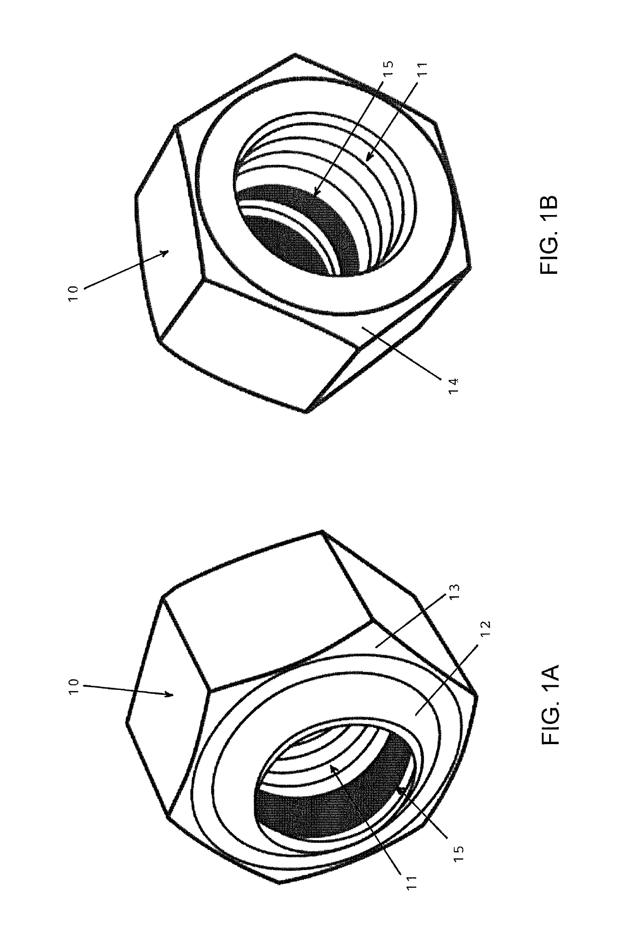
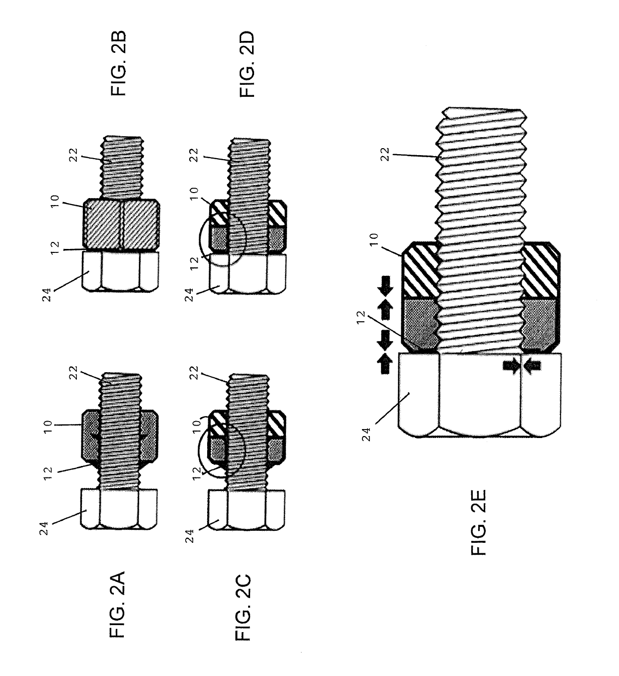
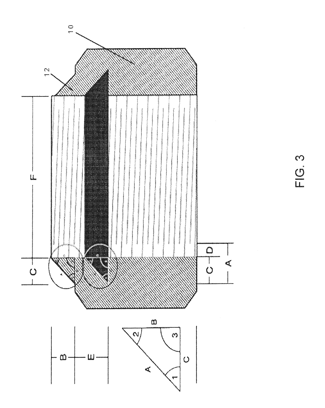
[0049]FIG. 1A is a front perspective view of a one-piece, self-locking nut in accordance with the present disclosure, and FIG. 1B is a rear perspective view thereof. The one-piece, self-locking nut has a nut body 10 with internal threading 11 for threading on a threaded shaft of a fastener bolt, and is integrally formed with external, crush-locking lips 12 provided on a forward contact face 13 of the nut body 10. The forward contact face 13 of the nut is typically beveled or provided with a slight convex curvature, while the rear face 14 of the nut is typically planar. The dark area 15 indicates a space for deformation of the crush-locking lips 12. When the nut is tightened down on an object (e.g., one or more plates being bolted together) on which the fastener bolt is used, the external, crush-locking lips 12 are forced inwardly and deform on the threaded shaft of the fastener bolt toward the internal threading 11 of the nut body, thereby locking (e.g., in a permanent fashion) the ...


PUM


Abstract

A self-locking nut includes a main-nut body and a deformable-nut body. The main-nut body has a recess leading into an interior threaded bore forming x turns of an internal thread therein. The deformable-nut body has an outer flange and an interior threaded bore forming y turns of an internal thread therein. The outer flange of the deformable-nut body is fixed to the main-nut body such that a relief space is formed between the deformable-nut body and the recess. A ratio of x:y is about 2:1.

Description

CROSS-REFERENCE TO RELATED APPLICATIONS[0001]This application is a continuation-in-part of prior application Ser. No. 14 / 918,035, filed Oct. 20, 2015, which is a continuation-in-part of application Ser. No. 13 / 916,532, filed Jun. 12, 2013, which claims the benefit of U.S. Provisional Application No. 61 / 804,693, filed Mar. 24, 2013, each of which is hereby incorporated by reference herein in its entirety.TECHNICAL FIELD[0002]The present disclosure relates generally to threaded nut fasteners and more specifically to one-piece self-locking nuts.BACKGROUND[0003]In many applications, it is desirable to have a threaded nut fastened on a threaded bolt with a permanent hold that will not loosen when exposed to high vibration environments. Conventionally, one or more locknuts may be fastened on the bolt behind the threaded nut to apply a locking force on the threaded nut to prevent it from loosening. However, the conventional use of locknuts requires added components to be used and manipulat...

Claims


Application Information

Patent Timeline
Patent Type & Authority Patents(United States)
IPC IPC(8): F16B39/34F16B39/12F16B39/02F16B39/286
CPCF16B39/34F16B39/026F16B39/122F16B39/286
Inventor LIMATOC, ARNOLD R.
Owner CRUSHLOCK INC
Why Eureka
Try Eureka