
Steady state differential roll moment control with automated differential lateral control

a roll moment control and automatic technology, applied in the field of helicopter control, can solve the problems of reducing the tip clearance of the rotor blade, affecting the tip clearance, and large roll moments,

Active Publication Date: 2019-06-25
SIKORSKY AIRCRAFT CORP
View PDF14 Cites 0 Cited by
  • Summary
  • Abstract
  • Description
  • Claims
  • Application Information

AI Technical Summary

Benefits of technology

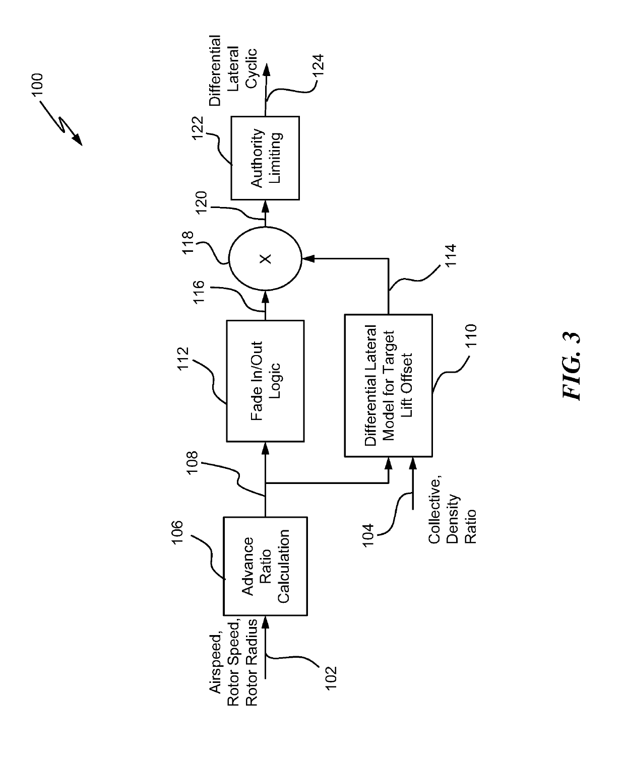
The patent describes a method for controlling the movement of a helicopter's rigid rotors to control the roll moment of the rotors. The method involves receiving a displacement command from a controller, measuring the longitudinal velocity, angular velocity, and air density ratio of the helicopter, and determining a ganged collective mixing command. A rotor advance ratio is then determined as a function of the longitudinal velocity and angular velocity. A corrective differential lateral cyclic command is determined to control the differential rotor roll moment to a desired value. The method can vary the targeted differential lateral cyclic based on aircraft flight condition, including minimum longitudinal velocity. The invention allows for more precise control of the helicopter's movement during flight maneuvers.

Problems solved by technology

These roll moments reduce tip clearance on the rotor blades.
Further, these roll moments are large and generally greater than what is needed to maneuver the helicopter.
Additionally, lift offset can adversely affect tip clearance.

Method used


Image

  • Steady state differential roll moment control with automated differential lateral control
  • Steady state differential roll moment control with automated differential lateral control
  • Steady state differential roll moment control with automated differential lateral control

Examples


Embodiment Construction

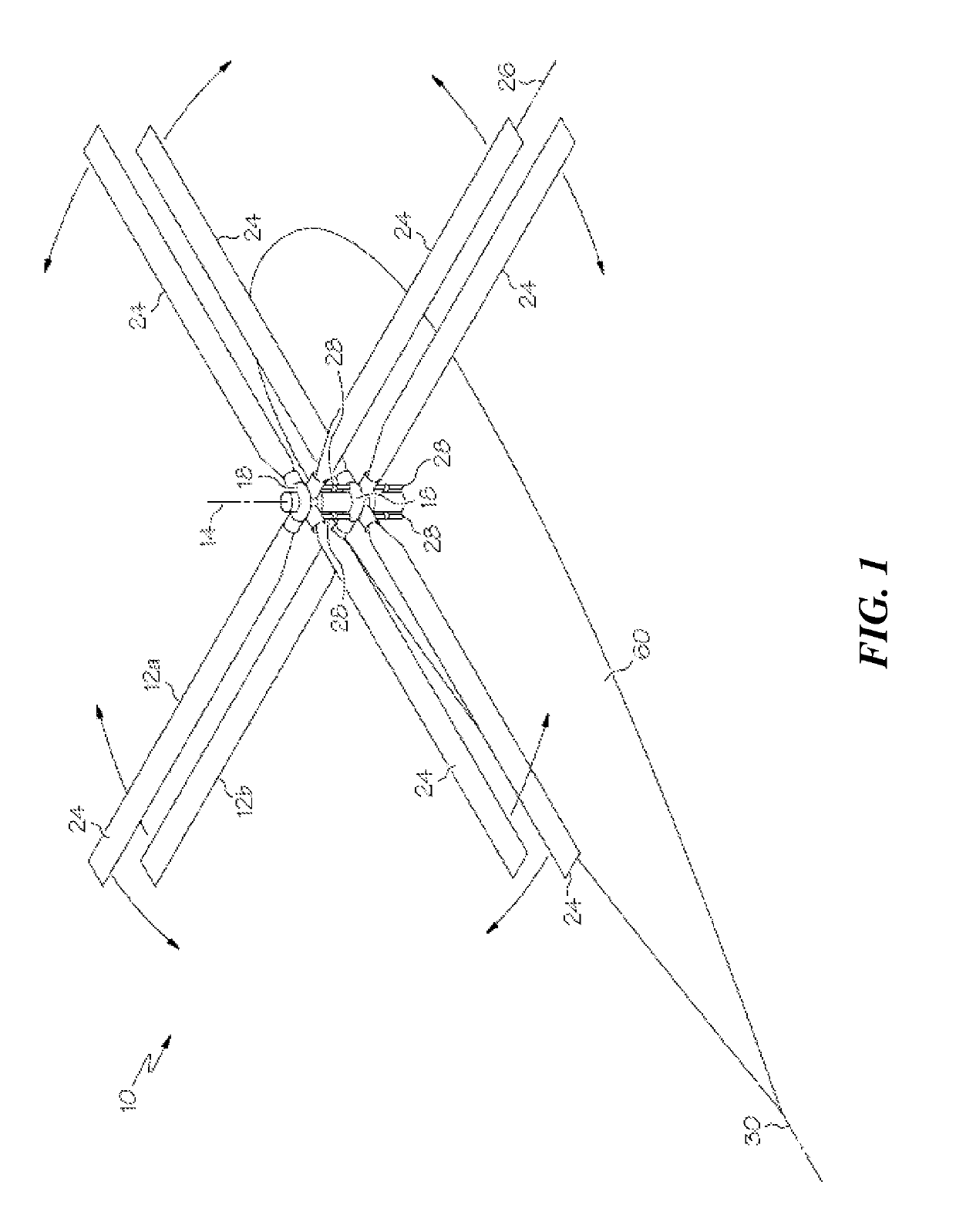
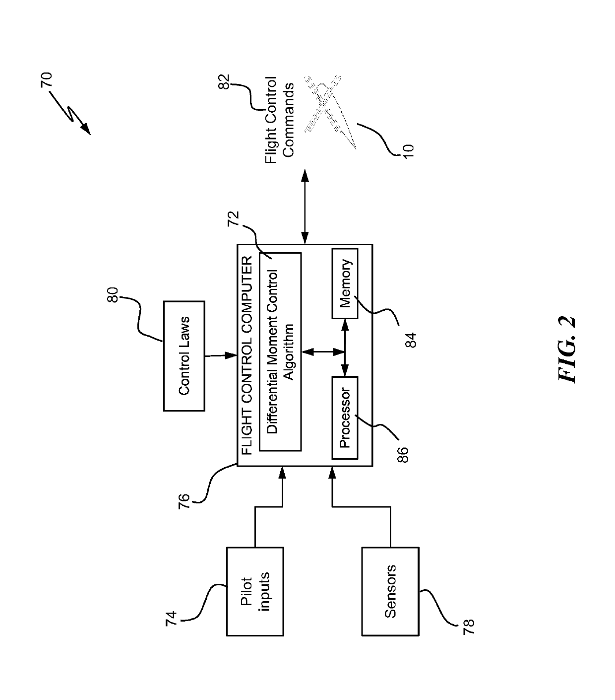
[0027]Shown in FIG. 1 is a schematic of an embodiment of rotary-wing aircraft such as, for example, a rigid dual-rotor helicopter 10. The helicopter 10 includes an airframe 60 and two rotors 12a and 12b arranged concentrically at the airframe 60 at a rotor axis 14. The rotors 12a and 12b counter-rotate such that, for example, when viewed from above, rotor 12a rotates in a counterclockwise direction and rotor 12b rotates in a clockwise direction. It is to be appreciated that, in other embodiments, the directions of rotation of the rotors 12a and 12b may be reversed. Each of the rotors 12a and 12b is connected to its respective conventional swashplate 18. Swashplate 18 is driven by one or more control servos 28 to move and / or tilt the swashplate 18 with respect to the rotor axis 14. Motion of the swashplate 18 along the rotor axis 14 will cause the blades 24 to vary pitch collectively relative to a blade axis 26, and tilting, either longitudinally or laterally, of the swashplate 18 re...


PUM


Abstract

A method for controlling a differential rotor roll moment for a coaxial helicopter with rigid rotors, the method including receiving, with a processor, a signal indicative of a displacement command from a controller; receiving, with the processor via a sensor, one or more signals indicative of a longitudinal velocity, an angular velocity of one or more rotors and an air density ratio for the helicopter; determining, with the processor, a ganged collective mixing command in response to the receiving of the displacement command; determining, with the processor, a rotor advance ratio as a function of the longitudinal velocity and the angular velocity; and determining, with the processor, a corrective differential lateral cyclic command for the rigid rotors that controls the differential rotor roll moment to a desired value.

Description

CROSS REFERENCE TO RELATED APPLICATIONS[0001]The present application is a National Stage Application claiming priority to Patent Application PCT / US2015 / 051914 filed on Sep. 24, 2015, which claims priority from U.S. Provisional Application Ser. No. 62 / 055,151 filed on Sep. 25, 2014, the contents of which are incorporated herein by reference in their entirety.BACKGROUND[0002]The subject matter disclosed herein relates generally to the field of helicopter control and to a steady state differential roll moment control with automated differential lateral control commands for rigid dual-rotor helicopters.DESCRIPTION OF RELATED ART[0003]Rigid dual rotor helicopters are those with two coaxial, counter-rotating rotors. Each rotor is controlled by a respective independent swash plate and can be commanded with both differential and ganged collective and cyclic controls. Rigid coaxial rotor helicopters must be designed with sufficient rotor spacing to ensure that the blade tips never touch duri...

Claims


Application Information

Patent Timeline
Patent Type & Authority Patents(United States)
IPC IPC(8): G05D1/08B64C27/80B64C27/10
CPCB64C27/80G05D1/0858G05D1/0808B64C27/10
Inventor FEGELY, CODYELLER, EREZWITTMER, KENNETH S.GREENFIELD, AARON L.KNAG, JOHN
Owner SIKORSKY AIRCRAFT CORP
Learn More