Flexible magnetic levitation bearing rotator rigidity damping identification method
A technology of magnetic suspension bearing and identification method, which is applied in the direction of mechanical bearing testing, measuring devices, instruments, etc., can solve the problems of rotor bending deformation, increase in identification error of magnetic suspension bearing stiffness damping, etc.
- Summary
- Abstract
- Description
- Claims
- Application Information
AI Technical Summary
Problems solved by technology
Method used
Image
Examples
Embodiment approach 1
[0110] Embodiment 1, simulation calculation identification:
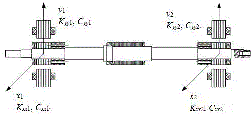
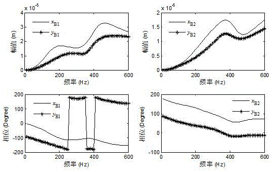
[0111] 1.1 Using Nelson-Timoshenko beam element, figure 1 It is the magnetic suspension bearing rotor coordinate system diagram. There are two left and right magnetic suspension bearings. The control force of each magnetic suspension bearing is decomposed into two directions of x and y that are perpendicular to each other. The K and C distributions represent stiffness and damping, and their subscripts indicate the directions of stiffness and damping. according to figure 1 Establish the rotor model of the flexible magnetic suspension bearing in the rotor coordinate system; set the support positions of the left and right magnetic suspension bearings to be located at node 20 and node 40 of the rotor finite element model, as shown in Figure 6 As shown; assuming that the stiffness and damping provided by the two magnetic suspension bearings are shown in Table 1. It is assumed that the disturbance force is the residua...
Embodiment approach 2
[0125] Embodiment 2, test identification:
[0126] 2.1 Add unbalanced mass to the magnetic bearing rotor, such as Figure 6 Shown; the specific information of the unbalanced quality is shown in the table;
[0127] Table 4 The unbalanced mass added in the test
[0128]
[0129] 2.2 Run the magnetic suspension bearing rotor system, starting from the speed of 50Hz, collect the displacement data at the magnetic suspension bearing every 10Hz; at the same time collect the rotor speed data.
[0130] 2.3 Fit the collected data with the first-order Fourier series through zero-phase filtering, and fit into the following formula:
[0131] y=a 0 +a 1 cos(xω)+b 1 sin(xω), (19)
[0132] At this time, the amplitude A and phase of the vibration The data can be obtained by the following formula, where is the rotational speed phase value,
[0133]
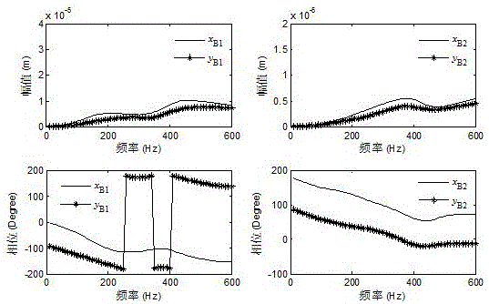
[0134] The experimental displacement vibration amplitude and phase data obtained at this time are as follows: Figure 7 shown;
...
PUM
 Abstract
Description
Claims
Application Information
 - R&D
- Intellectual Property
- Life Sciences
- Materials
- Tech Scout
- Unparalleled Data Quality
- Higher Quality Content
- 60% Fewer Hallucinations
Browse by: Latest US Patents, China's latest patents, Technical Efficacy Thesaurus, Application Domain, Technology Topic, Popular Technical Reports.
© 2025 PatSnap. All rights reserved.Legal|Privacy policy|Modern Slavery Act Transparency Statement|Sitemap|About US| Contact US: help@patsnap.com


