Remote fueling station with fuel pump enclosure

a fuel pump and remote fueling technology, applied in the field of remote fueling stations, can solve the problems of not being able to adapt the system described to the common commercially available fuel storage tank in a simple, low cost manner

Active Publication Date: 2019-07-02
WIEBE KYLE KEVIN OLIVER
View PDF10 Cites 0 Cited by
  • Summary
  • Abstract
  • Description
  • Claims
  • Application Information

AI Technical Summary

Benefits of technology

[0011]By providing an enclosure which can be supported on the fuel storage tank itself, a simple structure can be easily mounted to many varieties of tanks in a manner in which the mounts are restricted from access by unauthorized persons together with restricting access to the fuel pump and activation of the fuel pump.
[0018]In one embodiment, the enclosure comprises: i) a bottom panel defining a bottom side of a fuel pump compartment receiving the fuel pump therein; ii) a pair of support legs extending downwardly from the bottom panel to engage a top side of the tank; and iii) a depending leg portion which protrudes downwardly from the bottom panel to a bottom free end which is positioned lower than a bottom end of the support legs to prevent relative rotation between the enclosure and the tank about the supply pipe. Preferably the depending leg portion is adjustable in height relative to the enclosure.
[0030]By providing battery compartment which is accessible independently of the fuel pump compartment, the fuel pump and batteries can remain safely enclosed and isolated from one another to protect against explosions even when accessing the dispenser nozzle and the activation switch for dispensing fuel.

Problems solved by technology

Examples of remote fueling stations using solar energy are described in U.S. Pat. No. 5,692,647 by Brodie and WO2012 / 103498 by Fillner Construction, Inc., but the systems described are not readily adaptable to common commercially available fuel storage tanks in a simple, low cost manner, while providing some protection against theft or vandalism.

Method used


Image

  • Remote fueling station with fuel pump enclosure
  • Remote fueling station with fuel pump enclosure
  • Remote fueling station with fuel pump enclosure

Examples


Embodiment Construction

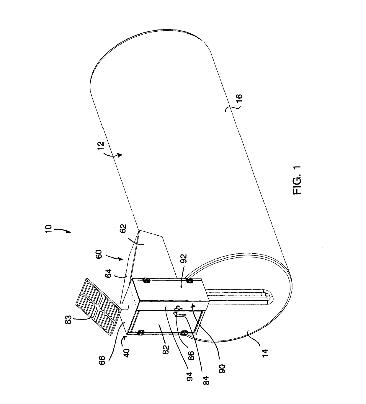
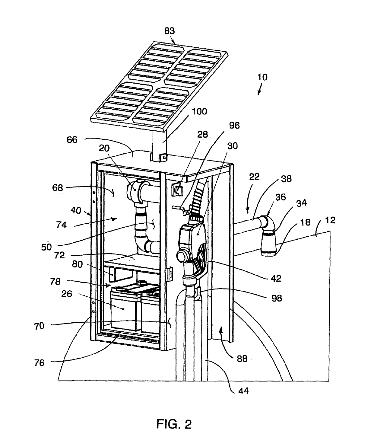
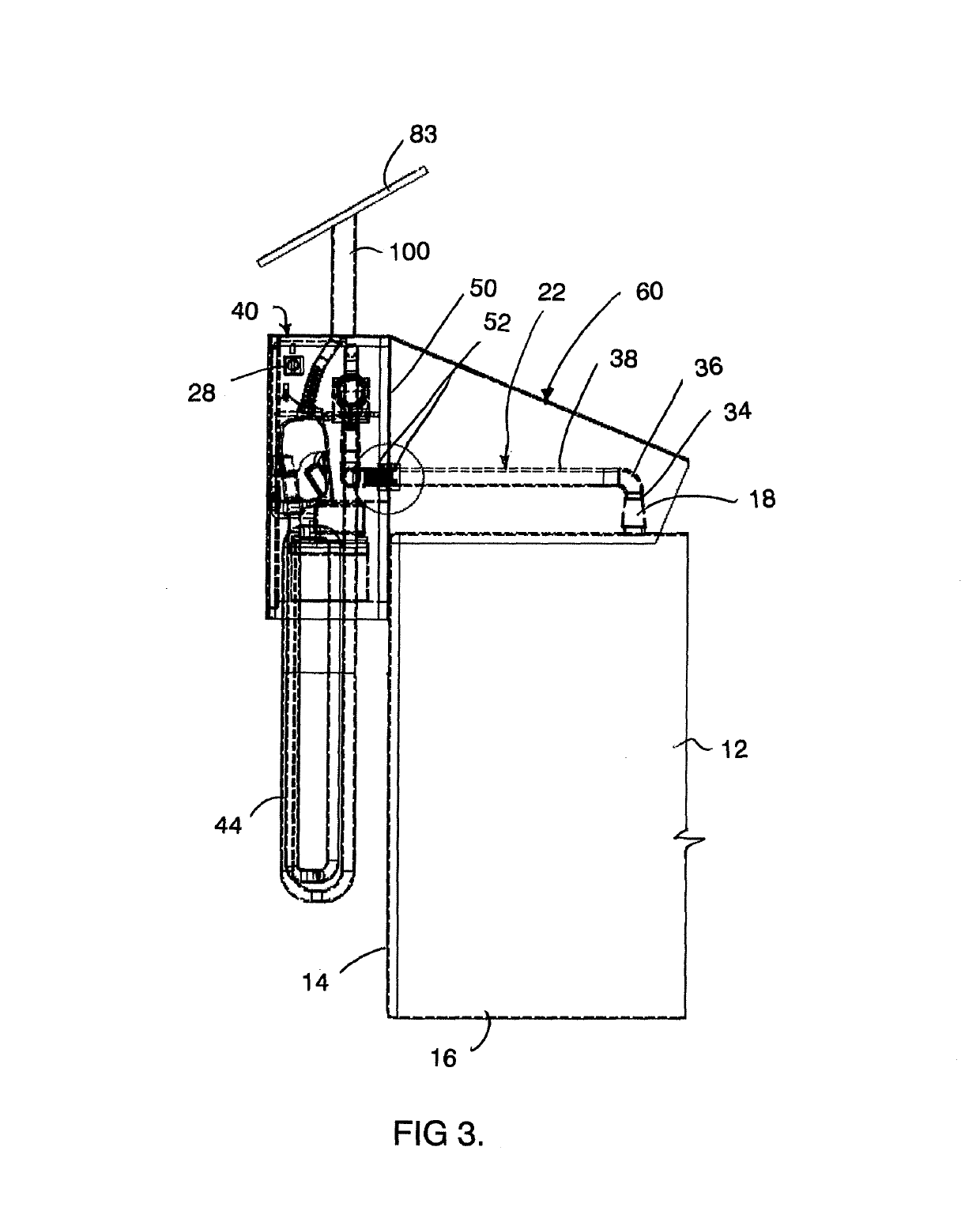
[0047]This invention relates to solar powered self-contained fueling stations. More particularly, this invention concerns the attachment to and above such a fueling station of a post-mounted solar power system, including a solar array providing shade for a shielded box holding a battery and a power control system with a power disconnect switch. Such post and solar power system may be folded down adjacent the fueling station, thus enabling easier transport of the fueling station. It also includes an area which the fueling pump and nozzle can be stored securely to eliminate any tampering that may occur when it is unsupervised. This unit is designed to be fitted on to most fuel storage tanks with modifying the size and lengths of the threaded pipe which connects the security cabinet to the fuel tank. Features of the system include: i) 1 solar panel with adjustable mount, ii) a solar charge controller with power disconnect switch, iii) a battery bank, iv) a fuel transfer pump, and v) a ...


PUM

PropertyMeasurementUnit
heightaaaaaaaaaa
poweraaaaaaaaaa
areaaaaaaaaaaa

Abstract

A remote fueling station for an above ground fuel storage tank has a fuel pump for dispensing a pressurize flow of fuel from the fuel tank to a dispenser nozzle. A lockable enclosure is supported on the fuel tank in fixed relation thereto by a threaded connection at an intermediate location along a rigid supply pipe connected between the fuel pump and the fuel tank. The enclosure includes a fuel pump compartment receiving the fuel pump therein and a battery compartment for receiving a battery of the fuel pump therein which is separate from the fuel pump compartment so that the battery is isolated from the fuel pump. A dispenser nozzle and an activation switch of the fuel pump can also be received within the enclosure so as to restrict access thereto by unauthorized persons. A solar panel is supported above the enclosure for recharging the battery.

Description

[0001]This application claims foreign priority benefits from Canadian Patent Application 2,894,071 filed Jun. 10, 2015.FIELD OF THE INVENTION[0002]The present invention relates to a remote fueling station including a fuel tank supported on the ground at a remote location and including a fuel pump for dispensing fuel from the tank to a dispenser nozzle, and more particularly the present invention relates to a fuel tank having an anti-theft enclosure supported thereon which receives the fuel pump therein and which supports a solar panel thereon for powering the fuel pump.BACKGROUND[0003]In many industries where work vehicles are operating in remote locations, for example agriculture, oil and gas, and / or mining, it is common to make use of a remote fueling station. A typical remote fueling stating includes a fuel storage tank, a fuel pump for pumping fuel from the storage tank to a dispenser nozzle, and a power supply for supplying power to the fuel pump. The power supply may take the ...

Claims


Application Information

Patent Timeline
Patent Type & Authority Patents(United States)
IPC IPC(8): B67D7/04H02S40/38B67D7/42B67D7/78H01M10/46B67D7/84B67D7/62
CPCB67D7/04B67D7/42B67D7/78H01M10/465H02S40/38B67D7/84H01M2220/10B67D7/62Y02E60/10Y02E70/30
Inventor WIEBE, KYLE KEVIN OLIVER
Owner WIEBE KYLE KEVIN OLIVER
Why Eureka
Try Eureka