
Method and device for measuring a DC voltage such as the voltage of a motor vehicle battery

Active Publication Date: 2019-07-02
VITESCO TECH GMBH
View PDF24 Cites 0 Cited by
  • Summary
  • Abstract
  • Description
  • Claims
  • Application Information

AI Technical Summary

Benefits of technology

The present invention aims to provide a method and device for measuring DC voltage with improved precision. This method and device can meet the precision requirements of "stop and start" type uses in the automotive field, such as ±200 mV, at a reasonable additional cost compared to current measuring devices. The quality of the correction can also be improved by increasing the number of bits of the analog-to-digital converter, which is done by using oversampling and running mean techniques during the acquisition of the voltages. This results in an increased accuracy of the measurements.

Problems solved by technology

The studies carried out in order to resolve this problem have shown that the main source of error resulted from the spread of the reference voltage Vref of the analog-to-digital converter.
Indeed, the spread of this reference voltage, of approximately ±2% for the common voltage regulators of the automotive field, is fully transferred to the measurement of the voltage of the battery, and results in a measuring error of approximately ±240 mV, which is greater than the measuring error accepted for some specific uses.
However, all of the current solutions lead to a considerable additional cost for the voltage regulators which notably impacts upon the cost of the electronic modules.
Yet, this adapting step implemented by means of a level adapter consisting generally, in the automotive field, of a divider bridge made up of resistors, represents an additional error source, the origin of which is the spread of the values of the components of the level adapter.
However, in addition to the increase in cost (by a factor greater than 5 for a divider bridge), it proves almost impossible to completely protect against the use of a non-compliant component, particularly with respect to the temperature drift coefficient thereof.

Method used


Image

  • Method and device for measuring a DC voltage such as the voltage of a motor vehicle battery

Examples


Embodiment Construction

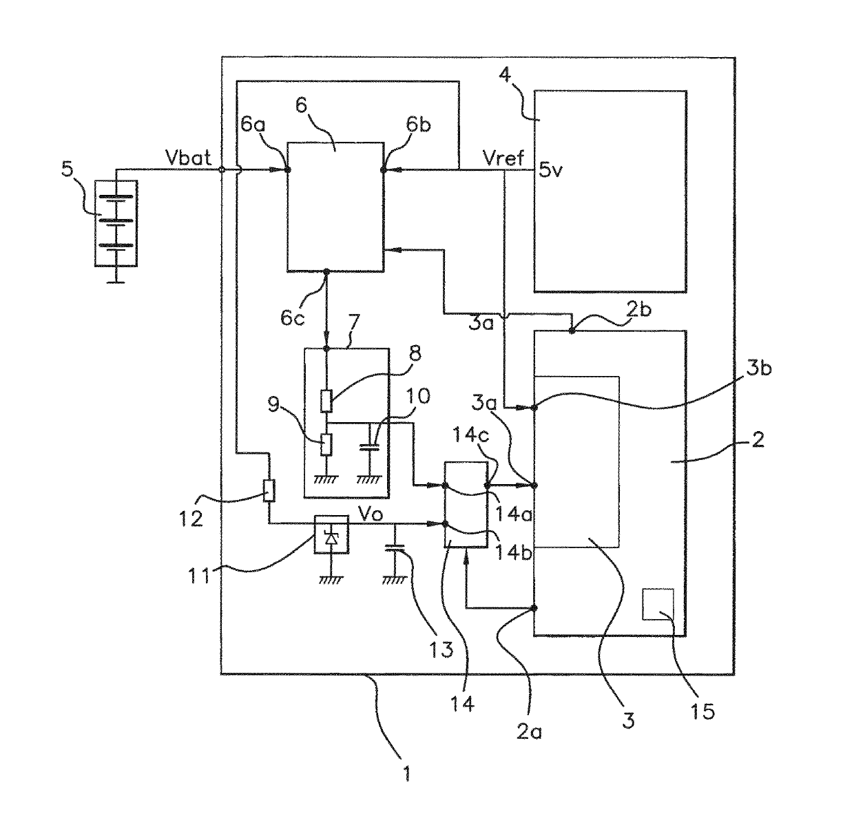
[0067]The electronic module shown in FIG. 1 consists of a computer 1, such as an injection control computer, intended to be on board a motor vehicle, and incorporating a device for measuring the voltage of the battery 5 of said vehicle.

[0068]This computer 1 includes, firstly:[0069]a microcontroller 2 incorporating, particularly, a memory 15, for example an EEPROM (Electrically Erasable Programmable Read-Only Memory) or flash EPROM memory, suitable for permanently retaining data, and an analog-to-digital converter 3 particularly including a channel 3a dedicated to measuring the voltage of the battery 5, and a channel 3b for receiving the reference voltage Vref of this analog-to-digital converter 3,[0070]a voltage regulator 4 for feeding all of the electronic components of the computer 1, and particularly suitable for delivering a reference voltage Vref equal to 5 V to the channel 3b of the analog-to-digital converter 3,[0071]a level adapter 7 having a gain k and consisting, in the ex...


PUM


Abstract

A method for measuring a DC voltage such as the voltage Vbat of a motor vehicle battery, according to which the voltage Vbat is converted into a digital value Nbat by an analog-to-digital converter (3) with which a reference voltage Vref is associated. A standard voltage Vo coming from a standard voltage source (11) is, furthermore, delivered regularly to the analog-to-digital converter, and the voltage Vo is converted into a digital value Nvo, then a digital value Ncor representing the value of the voltage Vbat is computed, such that Ncor=Co×(Nbat / Nvo), where Co=Ncor_max×(2N / Vbat_max)×(Vo / Vref), Ncor_max being a value selected for coding the maximum value of Ncor, Nbat_max a digital value resulting from the conversion of the maximum voltage Vbat_max to be measured, and N the number of bits of the analog-to-digital converter.

Description

BACKGROUND OF THE INVENTIONField of the Invention[0001]The invention relates to a method and a device for measuring a DC voltage such as the voltage Vbat of a motor vehicle battery.Description of the Related Art[0002]The common methods for measuring a DC voltage such as the voltage Vbat of a motor vehicle battery conventionally consist in converting the DC voltage Vbat into a digital value Nbat by means of an analog-to-digital converter with which a reference voltage Vref is associated.[0003]In relation to the automotive field, these measuring methods are implemented by means of measuring devices incorporated in an on-board electronic module, such as, for example, the injection control computer, and conventionally comprising:[0004]an analog-to-digital converter generally incorporated in the microcontroller of the electronic module,[0005]a voltage regulator for providing, in addition to the internal power supply of the electronic module, the analog-to-digital converter with a referen...

Claims


Application Information

Patent Timeline
IPC IPC(8): G01R19/25G01R31/3835G01R31/396
CPCG01R31/3835G01R19/2509G01R31/396
Inventor LUCCHESE, ALAIN
Owner VITESCO TECH GMBH
Learn More