Solar panel with flexible optical elements

a technology of flexible optical elements and solar panels, which is applied in the safety of solar heat collectors, photovoltaics, cosmonautic components, etc., can solve the problems of not disclosing the mechanism for storing or deploying the described concentrator cell array, and the coupling method of multiple solar panels, so as to increase the stiffness of the solar array, increase the resonance frequency, and increase the effect of rigidity

Active Publication Date: 2019-07-02
AIRBUS DEFENCE & SPACE NETHERLANDS
View PDF13 Cites 3 Cited by
  • Summary
  • Abstract
  • Description
  • Claims
  • Application Information

AI Technical Summary

Benefits of technology

[0010]The proposed array with repositionable concentrator reflector sheet members forms a selectively deployable solar concentrator, with reflective areas and PV cells provided on opposite surfaces of repositionable concentrator reflector sheet members. In the retracted state of the array, the concentrator reflector sheet members form a flattened arrangement with a reduced height. This yields a reduced stowage volume and greater mechanical robustness in the launch phase of the spacecraft (in stowed state). After launch of the spacecraft, the concentrator reflector sheet members of the array may be repositioned into the extended state, wherein the reflective areas on the front surfaces of the concentrator reflector sheet members form an efficient concentrator arrangement that is configured to receive solar radiation and to redirect this radiation towards the photovoltaic elements provided on the rear surfaces of the concentrator reflector sheet members. This concentration allows a reduction of the number of PV-cells, hence provides also a cost reduction. The proposed solar array arrangement is efficient and adaptable to various deployment conditions.
[0033]By bending the support panel about a transversal axis of curvature that is perpendicular to the elongation direction of the concentrator reflector sheet members, the latter will be forced to transition from their extended states to their retracted states due to anti-clastic bending energy. This anti-clastic effect helps to keep the concentrator reflector sheet members flattened against the mounting surface of the support panel in the stowed state of the solar array, thus obviating the need to apply further external forces (e.g. by means of a cover foil) to prevent the concentrator reflector sheet members from repositioning into their extended states.

Problems solved by technology

U.S. Pat. No. 5,344,496, however, does not disclose methods for coupling multiple solar panels, nor does it disclose mechanisms for stowing or deploying the described concentrator cell array.

Method used


Image

  • Solar panel with flexible optical elements
  • Solar panel with flexible optical elements
  • Solar panel with flexible optical elements

Examples


Embodiment Construction

[0055]The following is a description of certain embodiments of the invention, given by way of example only and with reference to the figures.

[0056]It should be understood that the directional definitions and preferred orientations presented herein merely serve to elucidate geometrical relations for specific embodiments. The concepts of the invention discussed herein are not limited to these directional definitions and preferred orientations. Similarly, directional terms in the specification and claims, such as “front”, “back / rear”, “top,”“bottom,”“left,”“right,”“up,”“down,”“upper,”“lower,”“proximal,”“distal” and the like, are used herein solely to indicate relative directions and are not otherwise intended to limit the scope of the invention or claims.

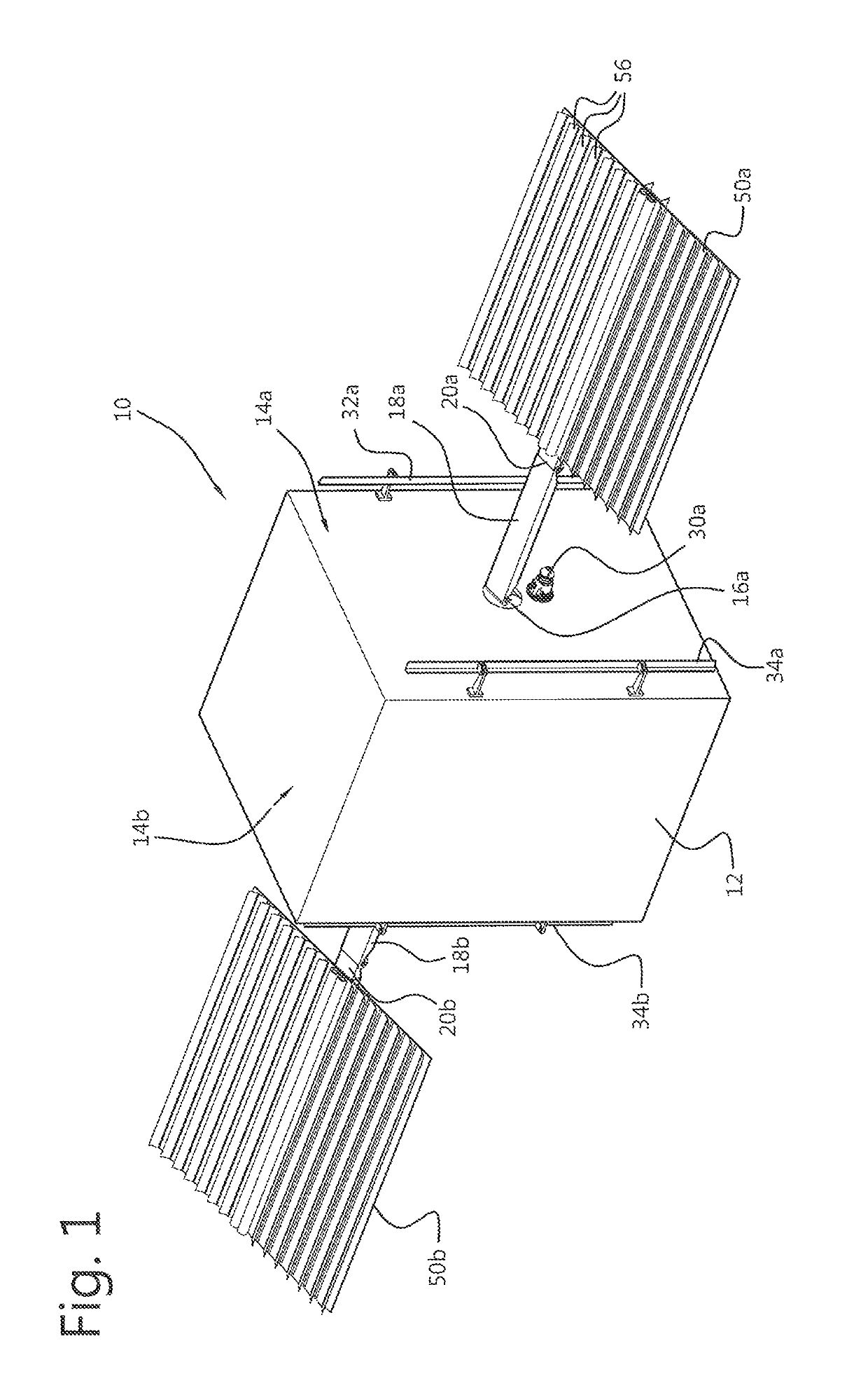
[0057]FIG. 1 schematically shows a perspective view of an embodiment of a spacecraft 10 according to an embodiment. In this example, the spacecraft is formed as a satellite unit 10. The satellite unit 10 includes a body 12 and a solar ...


PUM


Abstract

A solar array (50) for a spacecraft (10), comprising a solar concentrator that is provided with photovoltaic cells and reflective areas configured for reflecting solar radiation towards the photovoltaic cells, wherein the reflective areas and the photovoltaic cells are provided on opposite surfaces of concentrator reflector sheet members (56) that are repositionable from a retracted state wherein the concentrator reflector sheet members are in a substantially flat arrangement, to a extended state wherein the concentrator reflector sheet members are raised to allow the reflective areas to reflect solar radiation towards the exposed photovoltaic cells.Alternatively or in addition, the solar array may comprise a support panel, which may be at least partially flexible for retaining the support panel in a bent panel shape when the solar array is in the stowed state fixed at a position near a body of the spacecraft.

Description

CROSS REFERENCE TO RELATED APPLICATIONS[0001]This application claims priority from Dutch application number 2015387 filed on 2 Sep. 2015, which is hereby incorporated by reference in its entirety.TECHNICAL FIELD[0002]The invention relates to a solar array for a spacecraft, and to a spacecraft provided with such a type of solar array.BACKGROUND ART[0003]Solar arrays for use on spacecraft are known. In particular, such solar arrays are used for powering spacecraft based on photovoltaic (PV) conversion of solar radiation. Various solar cell arrangements for converting solar radiation into electricity have been proposed for space applications.[0004]In general, photovoltaic concentrator arrangements may be used to increase the energy output per unit area occupied by the photovoltaic cells. Such a concentrator arrangement is generally designed to receive solar radiation in an effective collection area and to redirect this received radiation towards the photovoltaic cells. As a result, the...

Claims


Application Information

Patent Timeline
Patent Type & Authority Patents(United States)
IPC IPC(8): B64G1/44H01L31/054B64G1/22H02S30/20H02S40/22H02S30/10H02S20/32F24S40/10
CPCH02S40/22B64G1/222B64G1/443H01L31/0547H02S30/10H02S30/20H02S20/32Y02E10/52F24S40/10
Inventor CRUIJSSEN, JOHAN HENDRIKDATEMA, PETRUS CORNELIS
Owner AIRBUS DEFENCE & SPACE NETHERLANDS
Why Eureka
Try Eureka