Hydro-pneumatic energy storage system

a technology of hydro-pneumatic energy storage and hydro-pneumatic energy, which is applied in the direction of machines/engines, mechanical equipment, greenhouse gas reduction, etc., can solve the problems of ineffective storage of energy and high cost of renewable energy from offshore turbine technologies in which wind, wave or tidal turbine is associated with an electrical power generator at offshore sites

Active Publication Date: 2019-07-09
UNIVERSITY OF MALTA
View PDF17 Cites 4 Cited by
  • Summary
  • Abstract
  • Description
  • Claims
  • Application Information

AI Technical Summary

Benefits of technology

[0018]Offshore wind, wave and tidal turbine technologies are usually based on systems in which a rotor of a wind, wave or tidal turbine drives an electrical generator that converts the rotational mechanical energy into electricity, which is then transported to shore via an electrical infrastructure consisting of cables and a transformer station. However, renewable energy from existing offshore turbine technologies in which the wind, wave or tidal turbine is associated with an electrical power generator is expensive at offshore sites located in relatively deep areas, and especially where wind speeds or wave and tidal currents are low. Moreover, when the electric energy is directly generated by the wind, wave and tidal turbines, this energy cannot be effectively stored so as to be dispatched during periods of power demand, as required. Integration of deep offshore floating turbine technologies with energy storage facilities can mitigate problems associated with the intermittent supply of natural energy by providing a regulated supply of pressurized deep sea water. Potential energy of pressurized deep sea water can, for example, be converted into electricity by allowing the pressurized deep sea water to flow through a hydraulic turbine connected to an electric generator.
[0057]The commercialization of floating offshore wind technologies in the near future will open endless opportunities to develop large offshore wind farms capable of meeting a considerable share of energy demand. Yet, technical problems originating from intermittency in the wind and other natural energy sources are regarded as major obstacles for the integration of large offshore natural sources into national grids. The integration of energy storage systems is therefore considered as a crucial development to facilitate the exploitation of power of natural energy sources on a wide scale. Minimizing the energy storage costs by optimizing energy storage efficiencies and minimizing the additional infrastructural costs required is critical to maintain wind energy production within feasible limits.

Problems solved by technology

However, renewable energy from existing offshore turbine technologies in which the wind, wave or tidal turbine is associated with an electrical power generator is expensive at offshore sites located in relatively deep areas, and especially where wind speeds or wave and tidal currents are low.
Moreover, when the electric energy is directly generated by the wind, wave and tidal turbines, this energy cannot be effectively stored so as to be dispatched during periods of power demand, as required.

Method used


Image

  • Hydro-pneumatic energy storage system
  • Hydro-pneumatic energy storage system
  • Hydro-pneumatic energy storage system

Examples


Embodiment Construction

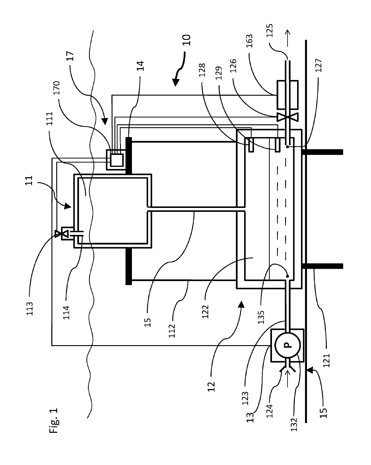
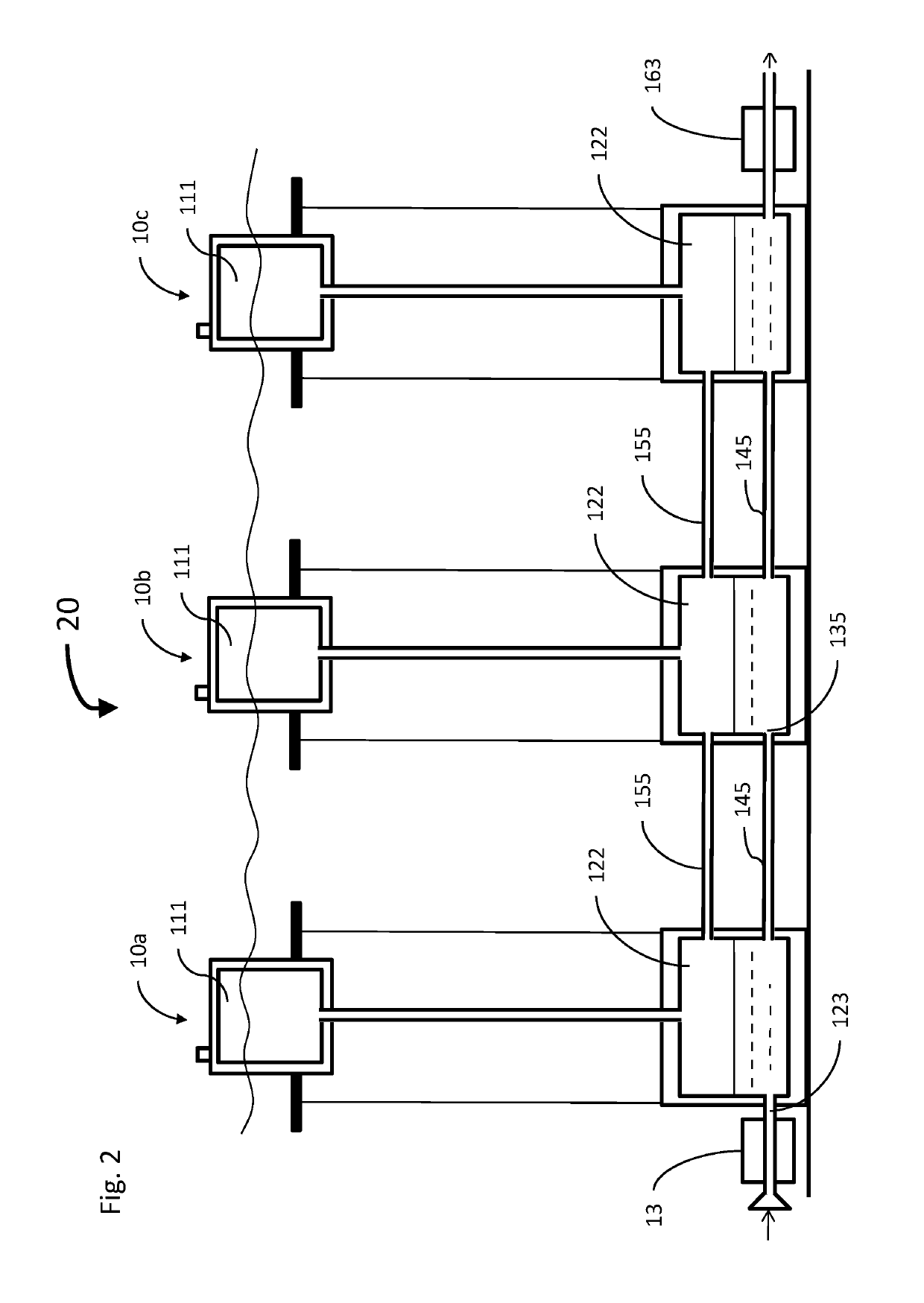
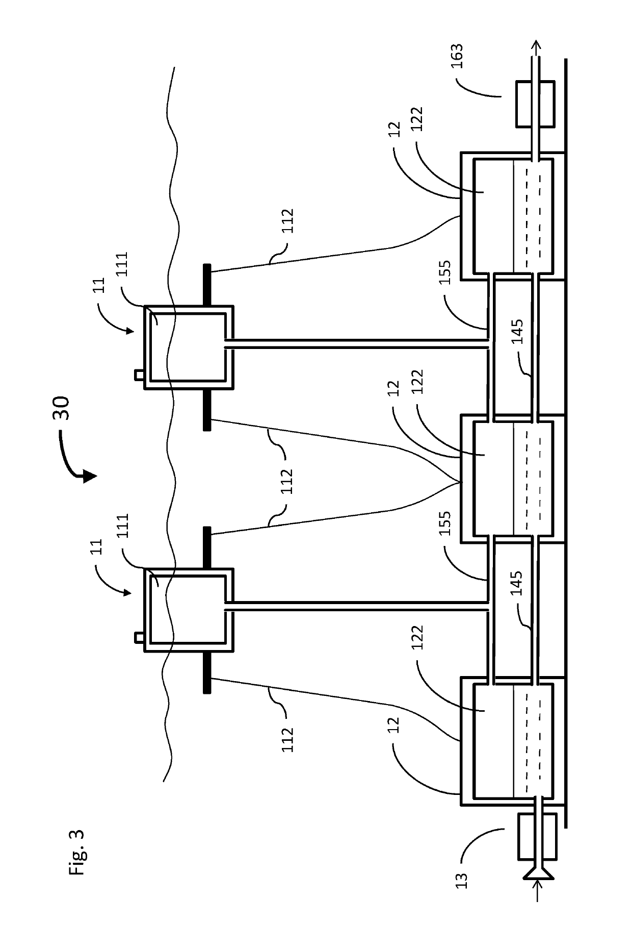
[0070]The principles and operation of the hydro-pneumatic energy storage system according to the present invention may be better understood with reference to the drawings and the accompanying description. It should be understood that these drawings are given for illustrative purposes only and are not meant to be limiting. It should be noted that the figures illustrating various examples of the system of the present invention are not to scale, and are not in proportion, for purposes of clarity. It should be noted that the blocks as well other elements in these figures are intended as functional entities only, such that the functional relationships between the entities are shown, rather than any physical connections and / or physical relationships. The same reference numerals and alphabetic characters are utilized for identifying those components which are common in the hydro-pneumatic energy storage system and its components shown in the drawings throughout the present description of t...


PUM


Abstract

A hydro-pneumatic energy storage system for deep sea water (DSW) is described. The system includes a floating support structure including a floating support platform, and a floating air chamber mounted on the floating support platform. The floating air chamber is configured for holding compressed air. The system also includes a sea-bottom mounted structure including a sea-bottom accumulator chamber configured for holding the compressed air and the DSW to store the DSW under pressure of the compressed air, and an air umbilical pneumatically interconnecting the floating air chamber with the sea-bottom accumulator chamber.

Description

FIELD OF THE INVENTION[0001]This invention relates to technologies generating energy, and more particularly to deep offshore floating turbine technologies with energy storage facilities.BACKGROUND OF THE INVENTION[0002]The world's demand for electric energy is continuously increasing. A vast amount of electric energy is currently generated by oil, gas, coal or nuclear plants. However, burning oil, gas and coal results in polluted air, and all of these fuel resources are rapidly diminishing. Nuclear energy requires the disposal of nuclear waste, which remains dangerous for centuries.[0003]Natural energy sources are effectively inexhaustible and are abundantly available throughout the world in various forms such as natural wind, solar, tidal and wave energy. Unfortunately, natural energy sources have an irregular nature, and peak demands for electrical energy in homes and in industry are usually out of phase with the availability of natural sources of energy.[0004]Wind energy conversi...

Claims


Application Information

Patent Timeline
Patent Type & Authority Patents(United States)
IPC IPC(8): F03D9/17F15B1/033F03B13/26F03B13/10F03D13/25F03D9/25F03D9/28F03B13/06F03D9/00
CPCF03D9/17F03B13/10F03B13/264F03D9/255F03D9/28F03D13/25F15B1/033F03B13/06Y02E60/17F03D9/008F05B2240/40F05B2240/93F05B2240/95Y02E10/22Y02E10/38Y02E10/725Y02E10/727Y02E60/15Y02E10/72Y02E60/16Y02E10/30Y02E70/30Y02E10/20
Inventor SANT, TONIOBUHAGIAR, DANIEL
Owner UNIVERSITY OF MALTA
Why Eureka
Try Eureka