Method and systems for diagnosing an engine

a technology for engine and diagnostic method, applied in the direction of electric control, combustion engines, machines/engines, etc., can solve the problems of lowering affecting the dc link voltage, etc., to improve the detection fidelity, reduce the cost and complexity of the system, and reduce the false positive

Active Publication Date: 2019-07-09
GE GLOBAL SOURCING LLC
View PDF20 Cites 1 Cited by
  • Summary
  • Abstract
  • Description
  • Claims
  • Application Information

AI Technical Summary

Benefits of technology

[0004]In this way, engine imbalance may be detected based on output from a sensor that measures a parameter indicative of generator output, such as the DC link voltage from the rectifier, engine speed, engine shaft torque, or alternator output voltage. By doing so, engine imbalance due to a degraded cylinder or fueling errors may be identified without the use of additional sensors, thus lowering the cost and complexity of the system. However, the DC link voltage may be coupled to various loads, such as the traction motors (via one or more inverters), and these downstream loads may affect the DC link voltage. The sources that contribute to the DC link voltage signal output from the DC link voltage sensor may be identified, and the detection of the imbalance may be performed when the sources are not contributing to the voltage and / or the detection may be adjusted to account for the additional content to the voltage signal by the other system components, thus lowering false positive indications and improving the fidelity of the detection.
[0005]In some examples, other sensor outputs may be analyzed to detect engine imbalance, such as an output from an engine speed sensor, an output from an engine shaft torque sensor, and / or alternator output voltage. As described above, these sensors may also experience contributions to their respective frequency components from sources other than engine imbalance, and thus these sources may be identified and the engine imbalance determination may be adjusted or delayed when the identified sources are determined to be contributing to the frequency content of the additional sensors. In doing so, false positive indications of engine imbalance may be avoided.

Problems solved by technology

By doing so, engine imbalance due to a degraded cylinder or fueling errors may be identified without the use of additional sensors, thus lowering the cost and complexity of the system.
However, the DC link voltage may be coupled to various loads, such as the traction motors (via one or more inverters), and these downstream loads may affect the DC link voltage.

Method used


Image

  • Method and systems for diagnosing an engine
  • Method and systems for diagnosing an engine
  • Method and systems for diagnosing an engine

Examples


Embodiment Construction

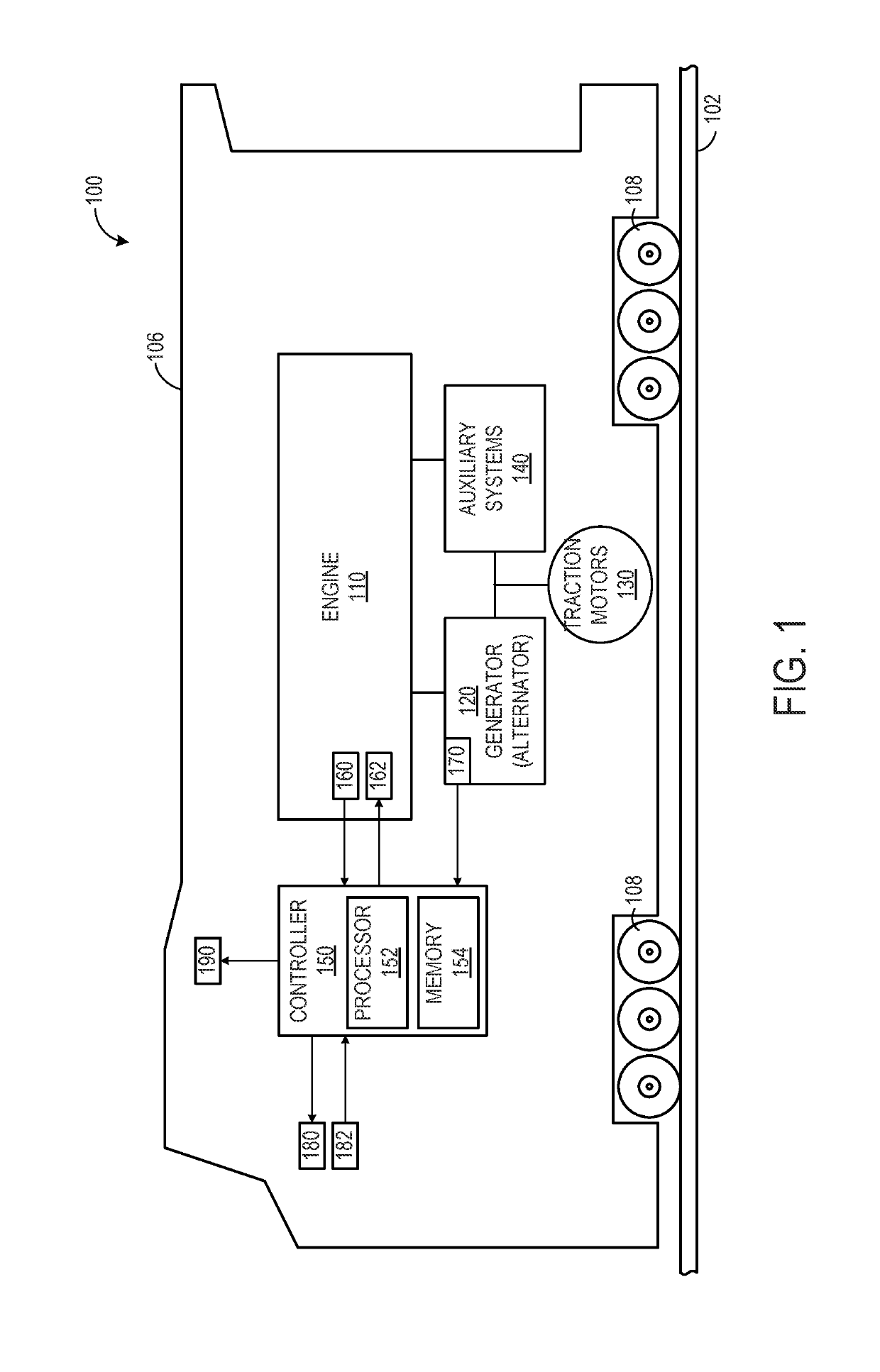
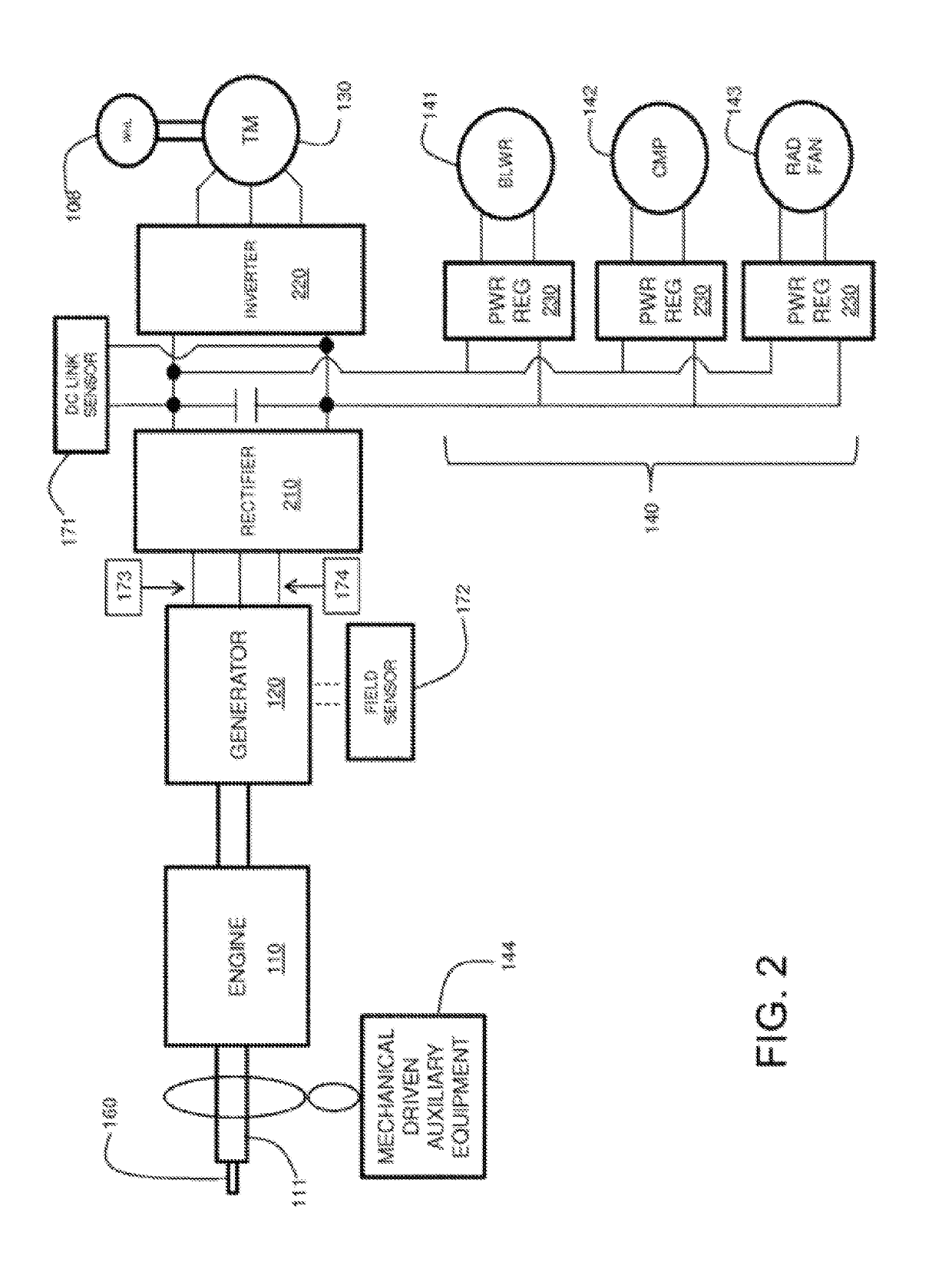
[0012]The following description relates to systems and methods for control of engine-related systems, e.g., for control of an engine or a system related to the engine based on a diagnosis of the engine. Furthermore, embodiments of the subject matter disclosed herein use engine and / or generator data, such as measured generator electrical parameters or generator data (e.g., DC link voltage, engine speed, engine shaft torque, alternator output voltage) derived from measured generator electrical parameters and / or engine parameters (e.g., speed), to diagnose conditions of an engine or auxiliary equipment and to distinguish between conditions and associated engine components and auxiliary equipment.

[0013]The engine may be included in a vehicle, such as a locomotive system. Other suitable types of vehicles may include on-highway vehicles, and off-highway vehicles other than locomotives, such as mining equipment, aircraft, and marine vessels. Other embodiments of the invention may be used f...


PUM


Abstract

A system includes a generator coupled to an engine and configured to generate electricity from rotational movement of a shaft of the engine, a sensor configured to measure one or more of a parameter of generator output, engine speed, or engine shaft torque, and a controller configured to detect engine imbalance based on a frequency content of a signal output from the sensor in response to a contribution to the frequency content from another component of the system being less than a threshold value.

Description

FIELD[0001]Embodiments of the subject matter disclosed herein relate to engines and control of engine-related systems.BACKGROUND[0002]A multi-cylinder engine includes a plurality of individual cylinders. Each cylinder combusts air and fuel to power the engine. Over time, individual cylinders and / or components coupled to the individual cylinders (e.g., exhaust valves) may become degraded. Further, because fueling may be individually controlled for each cylinder, fueling may become uneven between all the cylinders of the engine. If individual cylinders are not being fueled accurately (e.g., amount or timing of fuel injection), or cylinders become degraded, engine misfire may occur and / or the efficiency of the engine may decrease. Further, if the output of the cylinders varies such that the cylinders are unbalanced, this may put stress on engine components, such as the crankshaft, bearings, and / or cylinder connecting rods. While some engines may utilize individual cylinder pressure sen...

Claims


Application Information

Patent Timeline
Patent Type & Authority Patents(United States)
IPC IPC(8): G01M15/11F02D41/00F02D29/02G01M15/12F02D29/06F02D41/22F02B63/04F02D41/14F02D41/28B60L50/10
CPCG01M15/11F02B63/047F02D29/02F02D29/06F02D41/0085F02D41/0097G01M15/12F02D41/22Y02T10/40B60L50/10F02D41/1498F02D2041/288F02D2200/101F02D2200/1002
Inventor DAS, SUBHAS CHANDRAKUMAR, AJITH KUTTANNAIRCHANDRASEKARAN, SHANKARMUKHERJEE, RUPAM
Owner GE GLOBAL SOURCING LLC
Why Eureka
Try Eureka