Base member and an RFID member for 3D image creation

a 3d image and base member technology, applied in image enhancement, image data processing, instruments, etc., can solve the problems of difficult for any person to remove the base member from the element, and more difficult for an unauthorized person to remove the rfid member, so as to facilitate the acquisition and entry of users.

Active Publication Date: 2019-07-23
FARO TECH SWEDEN AB
View PDF6 Cites 1 Cited by
  • Summary
  • Abstract
  • Description
  • Claims
  • Application Information

AI Technical Summary

Benefits of technology

[0011]A second object of the invention is to improve the reliability of said process.DEFINITIONS
[0020]The fact that the cavity is adapted to hold an RFID member that prevents access to the fastening member arranged in the hole ensures that the base member cannot be removed from the element to which it is attached by means of said fastening member without also removing the RFID member from the base member. This arrangement makes it difficult for any person to remove the base member from the element. Most importantly, it reduces the risk that an unauthorized person, who perhaps does not understand the function of the base member, moves or removes the base member from the element.
[0028]The use of RFID members makes it easier for a user to acquire and enter information related to the scene. An authorized user may now use a handheld device, e.g. a smart phone, to acquire information directly from an RFID member or a database arranged to communicate with said RFID member. An authorized user may also use said handheld device to enter information into said RFID member or database.
[0029]Advantageously, at least a part of the base member comprises a magnetic material. This arrangement makes it easy to connect a reference member comprising a magnet to the base member as well as to remove the reference member from the base member. However, other types of connections are possible, such as a snap fit connection.

Problems solved by technology

This arrangement makes it difficult for any person to remove the base member from the element.
This arrangement makes it even more difficult for an unauthorized person to remove the RFID member.

Method used


Image

  • Base member and an RFID member for 3D image creation
  • Base member and an RFID member for 3D image creation

Examples


Embodiment Construction

[0045]The invention will now be described with reference to the accompanying drawings, wherein like characters denote like or corresponding parts.

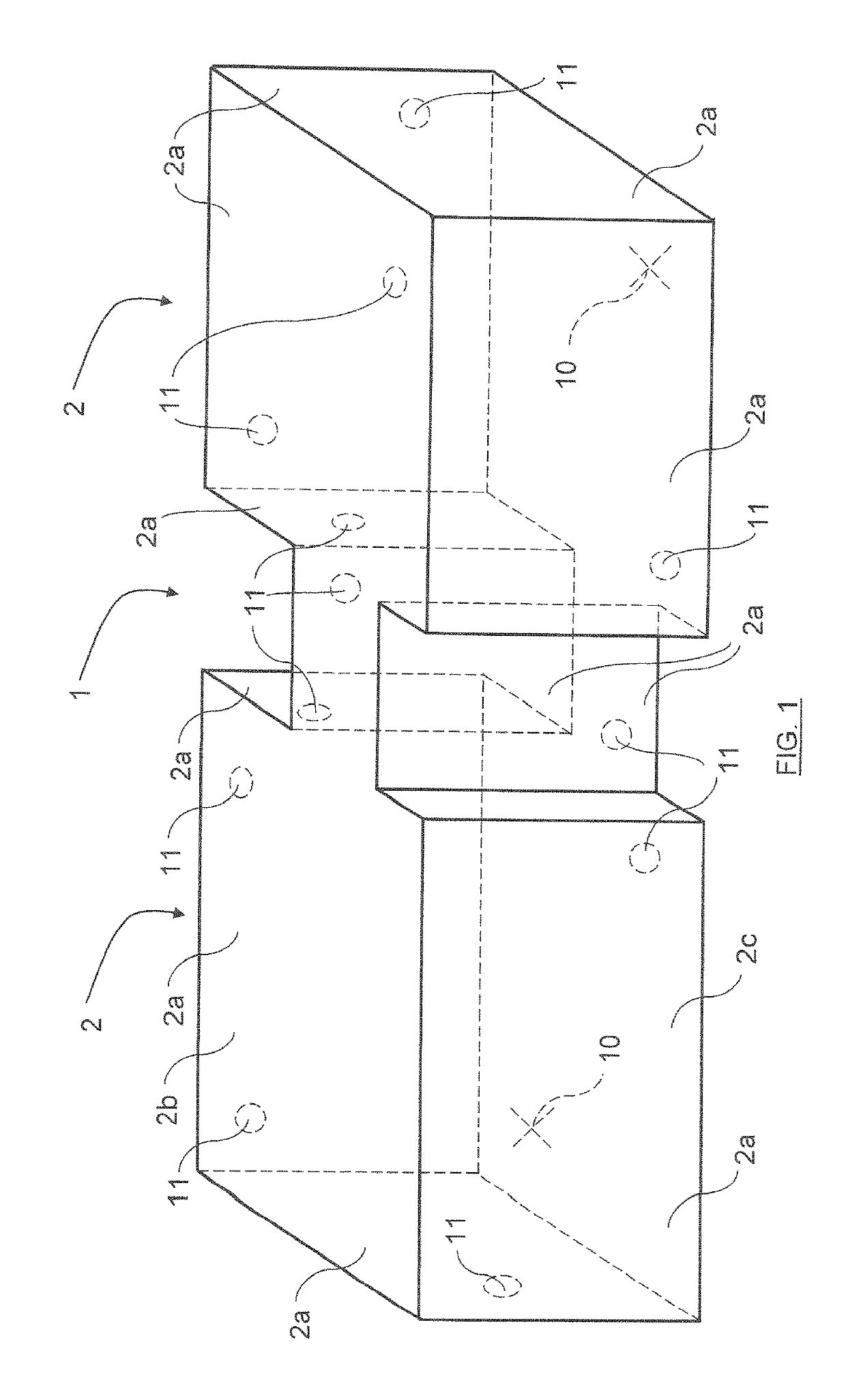
[0046]FIG. 1 shows a scene 1 comprising two rooms connected by a corridor. The scene comprises a plurality of elements 2 in the form of walls 2a, a ceiling 2b and a floor 2c. Additional elements in the form of fixed and movable objects (doors, closets, tables etc.) may also be included in the scene 1.

[0047]A method for generating a 3D image of the scene 1 and for determining coordinates of said 3D image in a geodetic frame will now be described with reference to FIG. 1.

[0048]In a first step, a user selects a plurality (in this embodiment two) of reference positions 10 within the scene 1. The reference positions 10 are selected so that every element 2 in the scene are visible from at least one of said reference positions 10.

[0049]Starting from a control point (located outside the scene) with known coordinates in a geodetic frame the user em...


PUM


Abstract

Disclosed is a base member for use with a plurality of interchangeable reference members. The base member is intended to be connected to an element of a scene and includes a first surface and a second surface, a hole adapted to receive a fastening member for connecting the base member to the element, and a connecting portion adapted to detachably connect a reference member to the base member. The base member also includes a cavity adapted to receive and hold an RFID member, which cavity is coaxial with the hole, connects the hole and the second surface and has a smallest diameter larger than the largest diameter of the hole. Also disclosed is an RFID member adapted to fit in the cavity of the base member to cover the hole in the base member.

Description

SUBJECT OF THE INVENTION[0001]The present invention relates to a base member for use with a plurality of interchangeable reference members to create a 3D image of a scene and to determine coordinates of said 3D image in a geodetic frame, which base member is intended to be connected to an element of the scene. The base member comprises a first surface arranged to face the element and a second surface arranged to face away from the element. The base member further comprises a hole adapted to receive a fastening member for connecting said base member to said element and a connecting portion adapted to detachably connect a reference member to the base member.[0002]The invention also relates to an RFID member for use with a base member according to the invention, which RFID member comprises an RFID tag.BACKGROUND OF THE INVENTION[0003]It is known to use a 3D scanner to create a 3D image of a scene, e.g. the inside of a factory or a room in a nuclear power plant.[0004]Base members are at...

Claims


Application Information

Patent Timeline
Patent Type & Authority Patents(United States)
IPC IPC(8): G06T17/05G01C15/00G06K19/077G01C15/02G01B21/04
CPCG06T17/05G01B21/042G01C15/02G06K19/0772G01C15/002G06T2207/10028G06T19/00G06T17/20G06T7/62
Inventor BERGQVIST, GORAN L.
Owner FARO TECH SWEDEN AB
Why Eureka
Try Eureka