Steerable catheter with flexing tip member

a catheter and tip technology, applied in the field of catheters with flexing tip members, can solve the problems of large outer diameters, large reusable and expensive resources of endoscopes and endoscopic equipment systems, and inability to move, etc., and achieve the effects of low cost, high accuracy, and simple us

Active Publication Date: 2019-07-30
SANOVAS
View PDF26 Cites 8 Cited by
  • Summary
  • Abstract
  • Description
  • Claims
  • Application Information

AI Technical Summary

Benefits of technology

[0008]Accordingly, it is an objective of the invention to provide a simple to use, lightweight, low cost, highly accurate, steerable catheter system where the catheter can be introduced into the body under direct and / or indirect visualization and can be made portable and disposable.
[0009]It is another objective of the invention to provide a steerable catheter that serves to eliminate the need to use complicated mechanical structures to articulate the distal tip of a catheter.
[0010]It is also an objective of the invention to provide a catheter having a sufficiently rigid body that provides needed torque and avoids kinking of the catheter during the insertion into bodily cavities.
[0011]It is a further objective of the present invention to provide a steerable catheter having a distal end that is able to bend at precise angles and planes so that the catheter can be maneuvered through very tight turns within the body, such as airway passages, vessel bifurcations, lumens, pleural cavities, and spaces within the tubular structures and capsular spaces of the body.
[0012]It is still another objective of the present invention to provide a steerable catheter where the maximum bend of the distal end of the catheter can be achieved with minimum pressures and forces.
[0013]It is a further objective of the present invention to use an imaging device used to help steer the catheter that is capable of providing a focused image regardless of how close the imaging device is positioned to target tissue.

Problems solved by technology

Endoscopes and endoscopic systems are, currently, a reusable and expensive resource in a physician's armamentarium.
In addition, the endoscopic equipment systems required to operate endoscopes are often large, bulky and relatively immobile devices.
A limitation in the utility of the flexible endoscope is that their outer diameters are often too large, their inner ‘working channel’ diameters are often too small, and their lengths are often inadequate to appropriately diagnose and treat the anatomy and corresponding pathologies found in the far reaches of the body's organs, vessels and spaces.
A further limitation of the utility of the flexible endoscope is that the articulation of the distal tip, and thus, its maneuverability, is typically accomplished by complicated mechanical structures that control the manipulating of the flexible endoscope's distal tip.
As such, the maneuverability is limited by the capabilities of the mechanical structures.
In addition, optimizing the external and internal diameters of the flexible endoscope is limited by the size and requirements of the mechanical structures.
However, the steerable catheters described above suffer from a number of disadvantages.
First, the structure of the known devices described above are still rather complex, requiring complicated mechanical structures to maneuver the devices.
Additionally, while these known devices provide for means to bend sections of the catheter or guidewire body, they do not provide reinforced structures to avoid kinking of the catheter or guidewire body during insertion into bodily cavities.
The devices described above are disadvantageous because, while they provide for articulation in a plurality of directions, it is not possible to limit the bending direction to only one plane.

Method used


Image

  • Steerable catheter with flexing tip member
  • Steerable catheter with flexing tip member
  • Steerable catheter with flexing tip member

Examples


Embodiment Construction

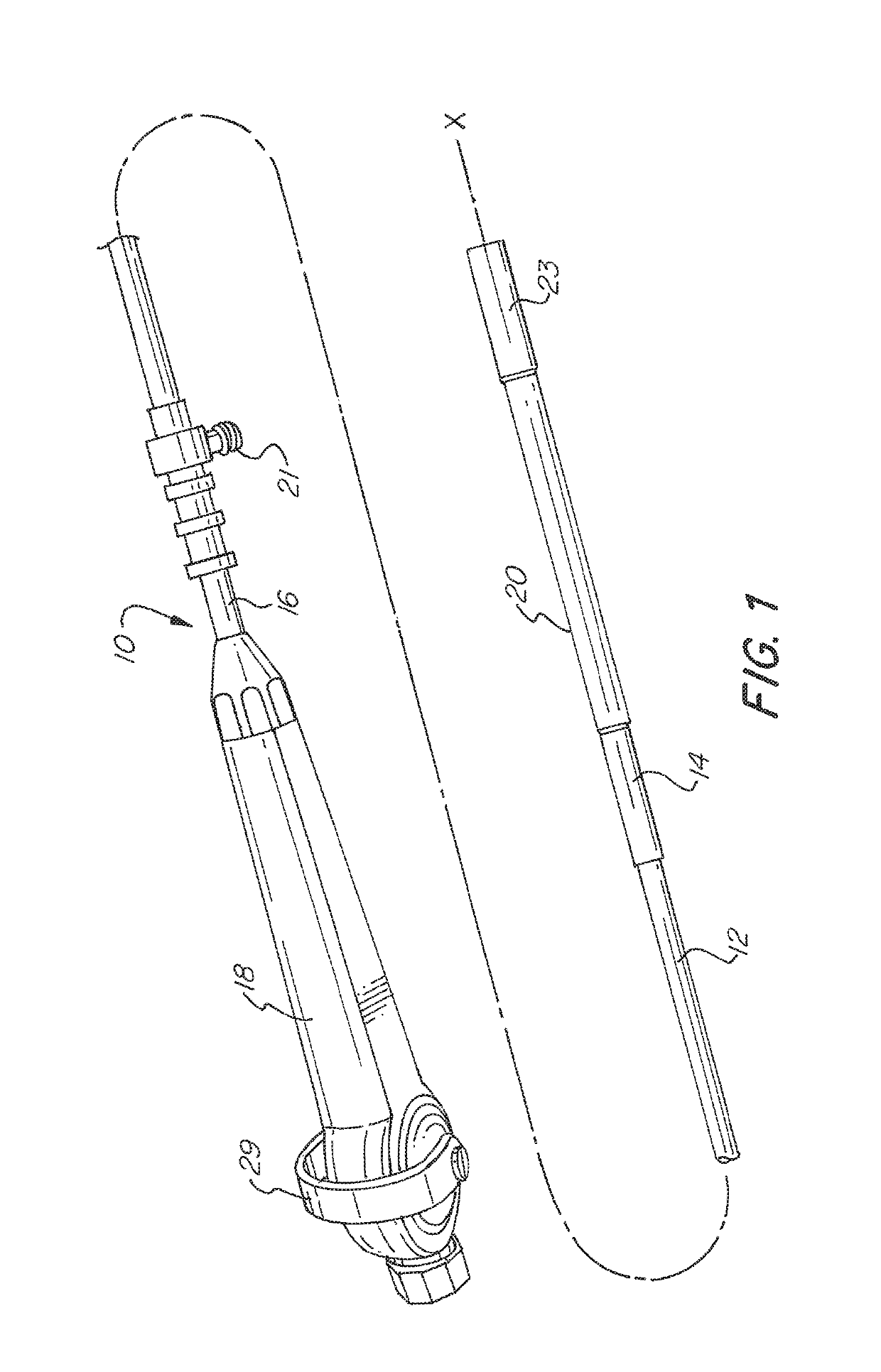
[0074]The basic components of one embodiment of a steerable catheter device in accordance with the invention are illustrated in FIG. 1. As used in the description, the terms “top,”“bottom,”“above,”“below,”“over,”“under,”“above,”“beneath,”“on top,”“underneath,”“up,”“down,”“upper,”“lower,”“front,”“rear,”“back,”“forward” and “backward” refer to the objects referenced when in the orientation illustrated in the drawings, which orientation is not necessary for achieving the objects of the invention.

[0075]As shown in FIG. 1, a steerable catheter, generally indicated at reference character (10), includes an elongated catheter body (12) having a proximal end (16) and a distal end (14). The catheter body (12) has a generally cylindrical body with an inner lumen. The catheter body (12) has a longitudinal axis (X-X) along which the length of the catheter body is defined.

[0076]The elongated catheter body (12) may be constructed from any suitable rigid or semi-rigid material, such as, for example...


PUM


Abstract

A steerable catheter device includes a catheter body, a flexing tip member coupled to a distal end of the catheter body and having a wall with a first plurality of arcuate slits and a second plurality of arcuate slits, the first and second plurality of slits being diametrically opposed and alternating with each other, and an actuator that bends the flexing tip member, wherein at least a portion of the catheter body includes a braided sheath, and wherein each of the first and second plurality of slits has two ends and a center positioned midway between the two ends, and wherein all of the first plurality of slits have centers positioned along a first axis substantially parallel to the longitudinal axis of the catheter body and all of the second plurality of slits have centers positioned along a second axis substantially parallel to the longitudinal axis of the catheter body.

Description

FIELD OF THE INVENTION[0001]The present invention relates to systems and methods for moving a catheter in bodily cavities. More specifically, the present invention relates to a catheter having a flexing tip member, which allows the catheter to be steered.BACKGROUND OF THE INVENTION[0002]In general, catheters are used in medical procedures in which tubular structures, lumens, pleural cavities or spaces of the body, such as airways, vessels, organs and joints, are diagnostically examined and / or therapeutically treated. Catheters, which can be introduced into the body through a natural orifice or through an incision, can deliver imaging devices, surgical instruments, implants, fluids, drugs, pharmacologic materials, biologic materials, biologic agents and therapeutics to treat or remedy various pathologies found therein. Catheters also guide and deliver other components, such as guide wires, scaffolds and tools, to the intended site within the body.[0003]Flexible, semi-rigid and rigid ...

Claims


Application Information

Patent Timeline
Patent Type & Authority Patents(United States)
IPC IPC(8): A61B1/00A61B1/045A61B1/05A61B1/06A61B1/005A61M25/01A61M25/00
CPCA61M25/0138A61B1/0052A61B1/0055A61B1/0057A61B1/00096A61B1/00105A61B1/05A61B1/0676A61B1/0684A61M25/0136A61B1/045A61M25/0147A61M25/005A61M25/0069
Inventor GERRANS, LAWRENCE J.GUNDAY, ERHAN H.HSIA, ALEXTUNG, JESSIE
Owner SANOVAS
Why Eureka
Try Eureka