Vehicle parking control device

a control device and vehicle technology, applied in electric vehicle charging technology, charging stations, transportation and packaging, etc., can solve the problems of driver discomfort in operating the vehicle, stress, driver discomfort, etc., to reduce stress at the time of parking, suppress unnecessary switching, and improve parking accuracy

Active Publication Date: 2019-07-30
HONDA MOTOR CO LTD
View PDF54 Cites 4 Cited by
  • Summary
  • Abstract
  • Description
  • Claims
  • Application Information

AI Technical Summary

Benefits of technology

[0010]The present invention has been devised taking into consideration the aforementioned problem, and has the object of providing a vehicle parking control device, which allows the driver to operate the vehicle at a time of parking without experiencing any sense of discomfort, and further is capable of improving parking accuracy.
[0022]According to the present invention, since the acceleration-OFF-state movement characteristics are switched when the parking operation is performed, parking accuracy can be improved. Furthermore, since the acceleration-OFF-state movement characteristics are switched not only by ensuring that the reference position of the vehicle is positioned inside of a predetermined range, but also by ensuring that another predetermined condition is satisfied, vehicle operations during parking are carried out without the driver experiencing any sense of discomfort.

Problems solved by technology

When the behavior of the vehicle by operation of the accelerator pedal is changed during parking, the driver experiences a feeling of discomfort when operating the vehicle.
When this takes place, the driver experiences a sense of discomfort in operating the vehicle and then feels stressed.

Method used


Image

  • Vehicle parking control device
  • Vehicle parking control device
  • Vehicle parking control device

Examples


Embodiment Construction

[0032]Below, a preferred embodiment of a vehicle parking control device according to the present invention will be described in detail below with reference to the accompanying drawings.

[Configuration of Non-Contact Charging System 10]

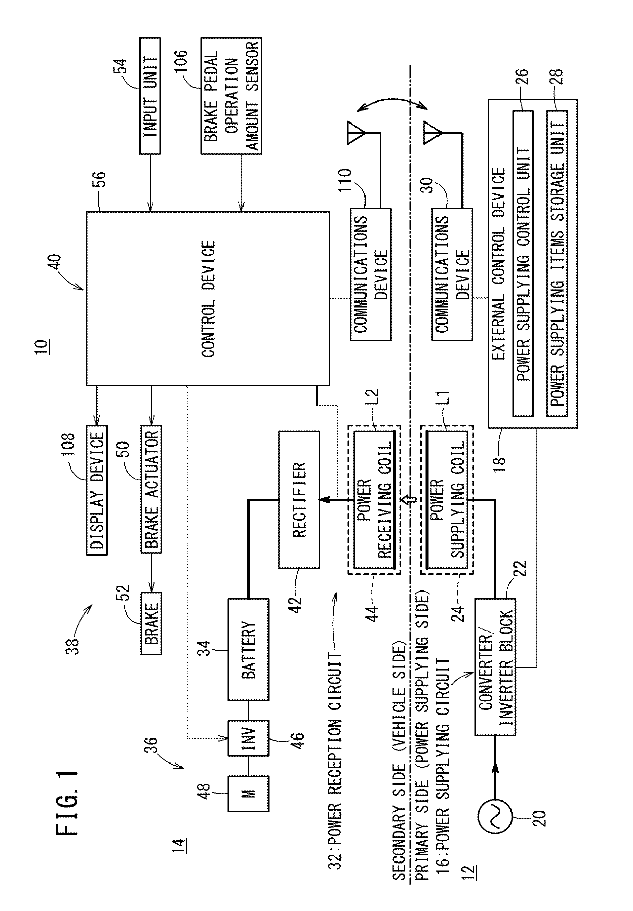
[0033]With reference to FIG. 1, a non-contact charging system 10 including a vehicle parking control device 40 according to the present invention will be described. The non-contact charging system 10 is constituted by an external power supplying device 12 of a primary side (power supplying side) disposed on a ground surface (road surface), and an electric vehicle 14 of a secondary side (power receiving side). In FIG. 1, the constituent elements on the lower side of the two-dot-dashed line indicate the external power supplying device 12, whereas the constituent elements on the upper side of the two-dot-dashed line indicate the electric vehicle 14. In the non-contact charging system 10, a battery 34, which is mounted in the electric vehicle 14, is charged...


PUM


Abstract

At a time that a parking operation is performed, a vehicle parking control device detects that a power receiving pad of an electric vehicle lies within a characteristics modifying range. Furthermore, the vehicle parking control device detects that other predetermined conditions are satisfied. In the case that the power receiving pad is positioned inside of the characteristics modifying range, and if all of the predetermined conditions have been satisfied, an acceleration-OFF-state movement characteristic of the vehicle, for example, a creep torque characteristic or a brake hydraulic pressure characteristic, is switched to an appropriate characteristic from a characteristic thereof at normal times.

Description

CROSS-REFERENCE TO RELATED APPLICATION[0001]This application is based upon and claims the benefit of priority from Japanese Patent Application No. 2015-044871 filed on Mar. 6, 2015, the contents of which are incorporated herein by reference.BACKGROUND OF THE INVENTION[0002]Field of the Invention[0003]The present invention relates to a vehicle parking control device that enables a vehicle to be stopped in positional alignment with a target position.[0004]Description of the Related Art[0005]Recently, electric vehicles, for example, an electric vehicle that is driven only by a storage battery, a hybrid vehicle equipped with an engine and an electric motor, a range extender vehicle, and a fuel cell vehicle equipped with a fuel cell, etc., have been developed. Together with the development of electric vehicles, techniques have been developed in relation to non-contact charging for charging the batteries of such electric vehicles in a non-contact manner.[0006]Non-contact charging possesse...

Claims


Application Information

Patent Timeline
Patent Type & Authority Patents(United States)
IPC IPC(8): B60L15/20B60L53/12B60L53/38
CPCB60L15/2063B60L53/38B60L53/12Y02T90/16B60L15/2009B60L2240/12B60L2240/642B60L2250/26B60L2260/22B60L2260/32Y02T10/645Y02T10/7005Y02T10/7072Y02T10/72Y02T10/7275Y02T10/7291Y02T90/12Y02T90/121Y02T90/122Y02T90/125Y02T90/14B60L53/122B60L53/126Y02T10/64Y02T10/70
Inventor NAKAGAWA, TOMOAKI
Owner HONDA MOTOR CO LTD
Why Eureka
Try Eureka