Marking strip

a technology of marking strips and strips, applied in the field of marking strips, can solve the problems of difficult to reliably produce endless strips, and achieve the effect of being particularly simple to produ

Active Publication Date: 2019-08-06
WEIDMULLER INTERFACE GMBH & CO KG
View PDF12 Cites 4 Cited by
  • Summary
  • Abstract
  • Description
  • Claims
  • Application Information

AI Technical Summary

Benefits of technology

[0009]In this way, it is possible to use plastics of different hardness for the regions of the marking plate with the writing field, and for the locking contour, respectively. The two-component co-extrusion process is a reliable and cost effective process, in particular in comparison to injection molding. With the extrusion process, an endless strip can easily be produced for rolling on a spool. Due to extrusion, in particular co-extrusion, the marking strips or the marking elements thereof can be used for printing using thermal transfer technology.
[0010]According to preferred embodiment, it is advantageous if the locking contour of each marking element is formed of the harder plastic material, in order to be able to snap it securely on the respective electrical device. In addition, it is advantageous if the marking plate is formed of the softer plastic material at least in the region of the writing field so that it can be printed on more precisely. The softer material facilitates the automatic adaptation to the printing head and it is also gentler on the printing head than a harder material. In addition, sink marks are prevented, and it is possible to design longer printable regions since they tilt less easily in the region of the printing head and / or do not lift off the heating bar. Furthermore, it is possible to select an easily printable material without having to ensure that the material is sufficiently hard for the locking function performed by the locking bars or locking feet.
[0011]It is also advantageous if the connecting region between the marking elements in each case includes a softer plastic region. This makes it possible, by pulling or compressing this region at the assembly site to compensate for smaller tolerances resulting from stacking the electrical devices. In addition, rolling the elements on the spool is facilitated.
[0012]Furthermore, it is advantageous if the connecting region between the marking elements includes at least one connecting bar. The connecting region between adjacent marking elements contains at least one hole, in particular an elongate hole which passes through the marking element in a snap-on direction perpendicular to the stacking direction thereof. Owing to the hole, the resilience of the connecting region can be increased or set in a targeted manner. In addition, the hole can be used as a sensing device for a sensor of a printer for triggering or for stopping printing.
[0015]In a preferred embodiment, the marking plate of the marking strip has no holes and / or marginal recesses. As a result, writings that span over devices can easily be implemented.
[0019]The production is particularly simple if the region that includes the first material is U-shaped in cross section, and the region that includes the second harder material is generally V-shaped.

Problems solved by technology

In this process, it is particularly difficult to reliably produce an endless strip for rolling onto a spool from the individual injection molded strips without misalignment.

Method used


Image

  • Marking strip
  • Marking strip
  • Marking strip

Examples


Embodiment Construction

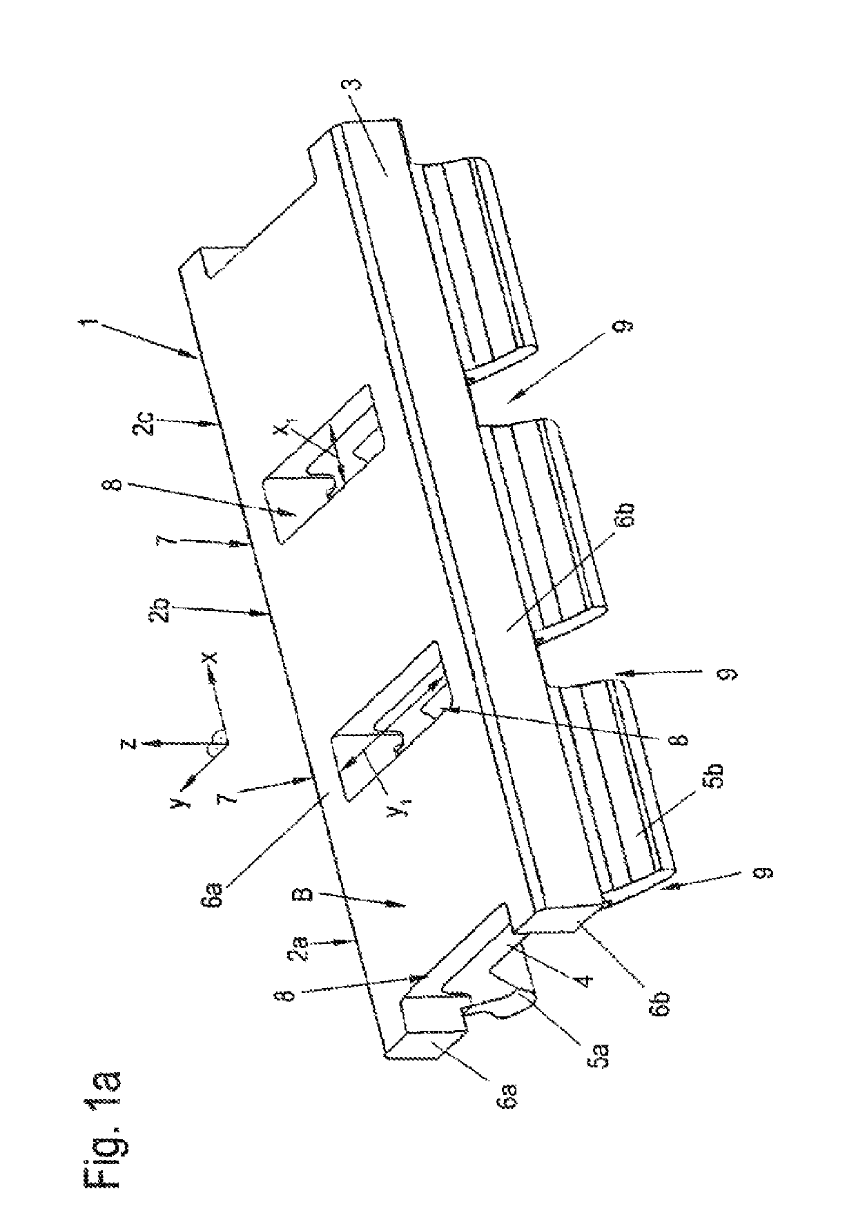
[0031]FIG. 1a shows a marking strip 1 which includes a plurality or variety of marking elements 2a, b, c, that are connected to one another.

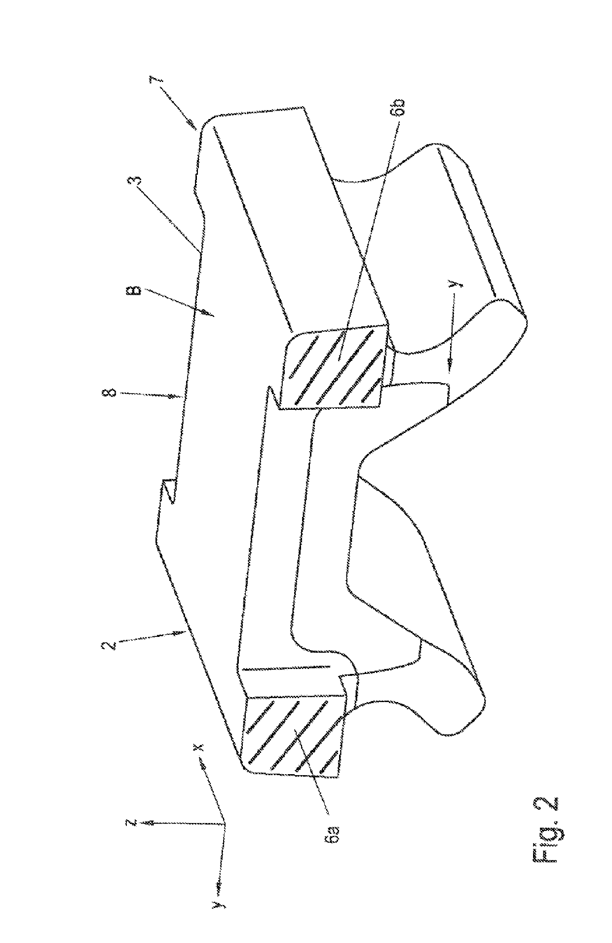
[0032]The marking strip 1 having the marking elements 2 is designed for marking electrical devices, in particular electrical devices that can be arranged next to each other, preferably terminal blocks that are arranged next to each other. For this purpose, each of the marking elements 2 has a marking plate 3 having at least one writing field or area which can be provided with information thereon. Preferably, the writing field 3 is designed in order to be printed on with a printer.

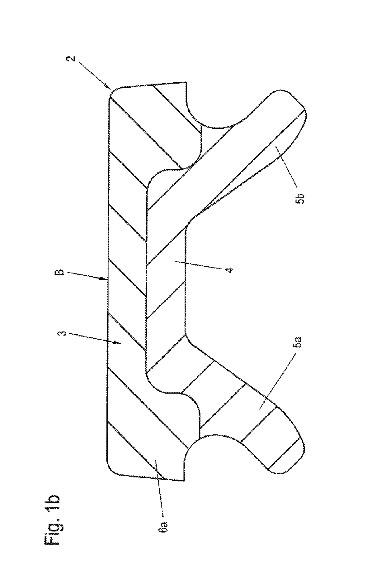
[0033]Each of the marking elements 2 has, on the side facing away from the writing field, a locking contour 4 integrally connected with the respective marking plate 3 for a snap-on connection to a corresponding locking contour (not shown) of a corresponding electrical device.

[0034]The locking contour 4 of each marking element is formed by two locking bars 5a, 5b, which ...


PUM

PropertyMeasurementUnit
degree of hardnessaaaaaaaaaa
areaaaaaaaaaaa
coloraaaaaaaaaa

Abstract

A marking strip has a plurality of marking elements which are connected to each other by a connecting region. The marking strip having the marking elements is designed to mark electrical devices, in particular electrical devices that can be arranged next to each other such as terminal blocks. Each of the marking elements has a marking plate including at least one writing field which can be provided with information. On the side facing away from the writing field, each of the marking elements has a locking contour which is integrally connected with the marking plate. The marking strip is formed of at least two different plastic materials of different hardness. The locking contour of each marking element is formed of a harder plastic material, and the marking plate is formed of a softer plastic material at least in the region of the writing field. The connecting region between the marking elements is formed of the softer plastic material.

Description

[0001]This application is a § 371 National Stage Entry of PCT International Application No., PCT / EP2015 / 069813 filed on Aug. 31, 2015. PCT / EP2015 / 069813 claims priority of DE 102014113075.8 filed Sep. 10, 2014 and DE 102015109020 filed Jun. 8, 2015. The entire contents of these applications are incorporated herein by reference.BACKGROUND OF THE INVENTION[0002]The invention relates to a marking strip.[0003]From DE 20 2007 012 606 U1, it is known to produce markers for electrical lines, cables and wires by a two-component injection molding process, in which a marking plate is formed of a harder plastic than spring elements arranged on the marking plate for fastening the marker to the cable.[0004]If a plurality or a variety of electrical devices such as terminal blocks are arranged next to each other on an assembly base, each device having a locking contour such as a locking recess, the marking process is simplified if, instead of a plurality of completely separated marking elements su...

Claims


Application Information

Patent Timeline
Patent Type & Authority Patents(United States)
IPC IPC(8): G09F3/00H01R13/46G09F3/02B29C48/154B29C48/16G09F7/06H01R9/26G09F3/20G09F3/16G09F3/06B29C48/18B29C48/12B29C48/00B29K55/02B29K69/00B29K75/00B29K77/00B29K101/12B29L9/00B29L31/00
CPCB29C48/0022B29C48/154B29C48/16B29C48/18G09F3/02G09F3/0295G09F3/06G09F3/16G09F3/205G09F7/06H01R9/2683H01R13/465B29C48/12G09F2003/0263B29K2055/02B29K2069/00B29K2075/00B29K2077/00B29K2101/12B29K2995/007B29L2009/00B29L2031/7232G09F2003/0201G09F2003/0202G09F2003/0222
Inventor SPEITH, MARKUSWIENEKE, ANDREASSCHREIBER, DITMARRIEKE, THORSTENBETT, THORSTENSCHNEIDER, MAXIMILLIANROSIN, MAXIMILIANHULSMANN, RENE
Owner WEIDMULLER INTERFACE GMBH & CO KG
Why Eureka
Try Eureka