Advanced curtain wall mullion anchoring system

a technology of curtain wall and mullion, which is applied in the direction of walls, constructions, building components, etc., can solve the problems of time-consuming process, and achieve the effect of accurate placement and simplified manufacturing extrusion process

Active Publication Date: 2019-08-06
TING RAYMOND M L
View PDF73 Cites 1 Cited by
  • Summary
  • Abstract
  • Description
  • Claims
  • Application Information

AI Technical Summary

Benefits of technology

[0008]This invention utilizes an anchoring device installed on a cured concrete floor slab and an integral mullion connector engaged with both the anchoring device and a mullion. Because the anchoring device can be installed after the concrete floor slab is cured, the anchoring device can be accurately placed at the proper in-and-out position using a reference line based on a fixed distance between a building feature (e.g., a spandrel column line) and the mullion. The anchoring device can be accurately placed at the proper left-and-right position by marking the mullion center position on the reference line. Since in-and-out construction tolerance adjustment is completed simply by securing the anchoring device at the proper in-and-out position after the concrete floor slab is cured, in-and-out adjustability among parts of the mullion anchoring system and the mullion is unnecessary. Thus, the mullion connection clip and the mullion connection bridge of the systems disclosed in U.S. Pat. No. 9,683,367 and U.S. Patent Application Publication No. 2017 / 0241133 may be combined into an integral member, hereinafter referred to as a mullion connector. The use of an integral mullion connector simplifies both the manufacturing extrusion process and the mullion anchoring system installation process. Left-and-right adjustability among parts of the mullion connection system and the mullion also is unnecessary, and an interlocking feature may be provided between the mullion connector and anchoring device to restrict left-and-right movement without using a fastener. The mullion connector is slidably engaged with the mullion to automatically permit automatic placement of the mullion connector at the proper up-and-down position. Thus, three-way construction tolerance adjustments are automatically made without the need for further adjustments during mullion erection.

Problems solved by technology

The second and the third adjustments can be done simultaneously, however, it is a time consuming process since it must be done for each individual mullion.

Method used


Image

  • Advanced curtain wall mullion anchoring system
  • Advanced curtain wall mullion anchoring system
  • Advanced curtain wall mullion anchoring system

Examples


Embodiment Construction

[0019]Reference will now be made in detail to the preferred embodiments of the present invention, examples of which are illustrated in the accompanying drawings.

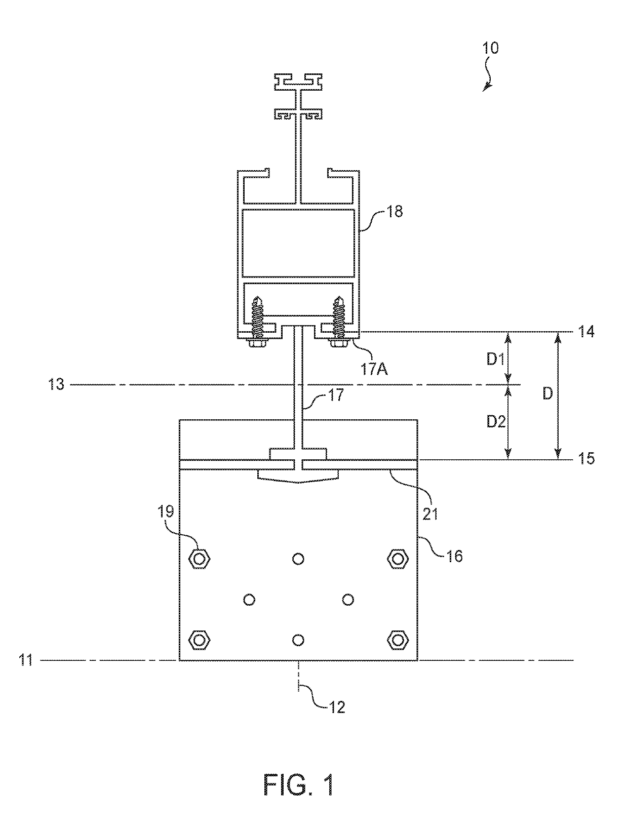
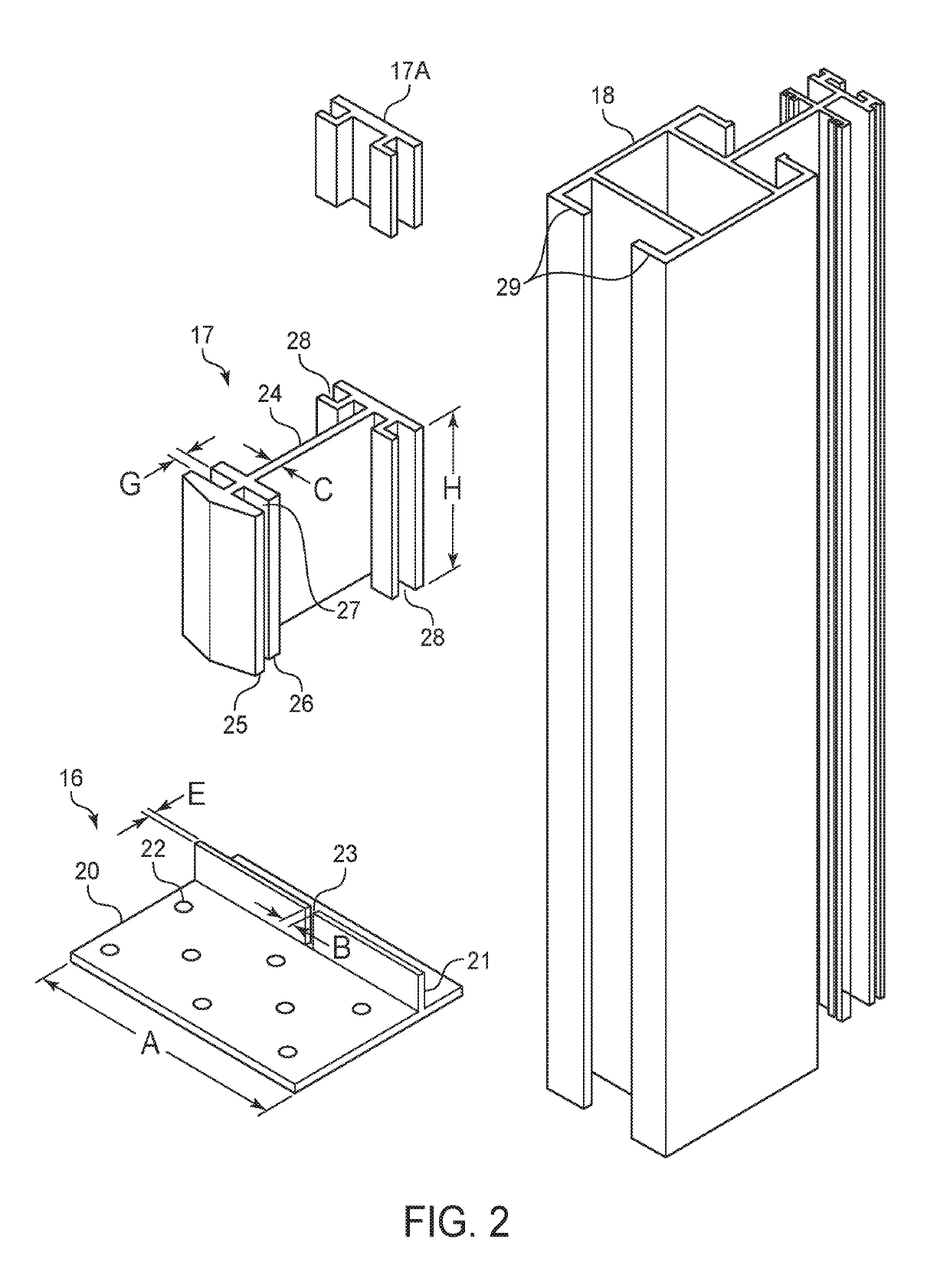
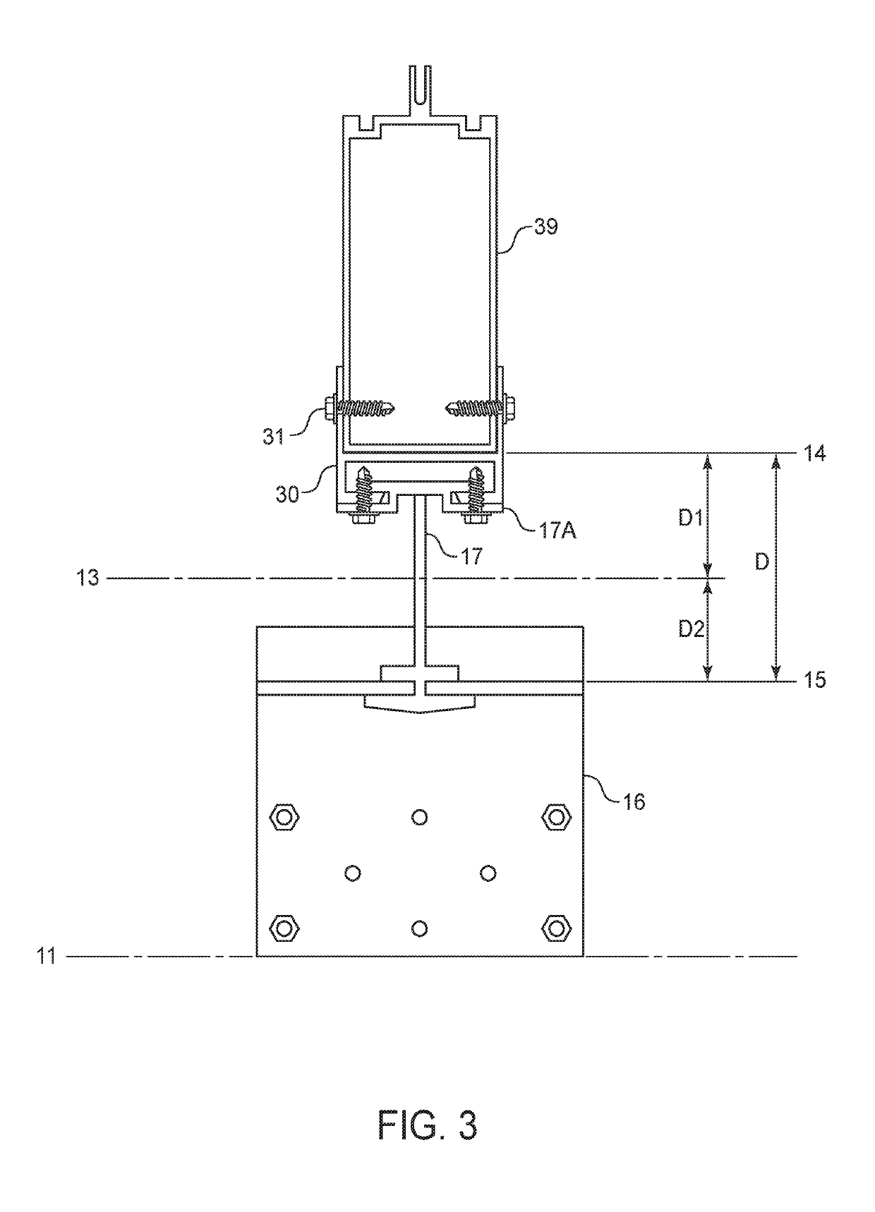
[0020]Preferred mullion anchoring systems of the present invention include an anchoring device anchored to a concrete floor slab and a mullion connector connecting the anchoring device to a mullion. The anchoring device has a horizontal leg secured to the floor slab and an upstanding load resisting lip designed to resist negative wind loads and optionally for resisting positive wind loads. The anchoring device may be installed on a cured concrete floor slab using concrete anchors.

[0021]The mullion connector is slidably engaged with the mullion using matching male and female joints, as described in U.S. Patent Application Publication No. 2013 / 0186031, which is incorporated by reference herein, such that the mullion connector may engage the mullion and slide along the length of the mullion. The ability to slide the engaged mul...


PUM


Abstract

A curtain wall mullion anchoring system that does not require adjustability among the anchoring system components and the mullion to account for construction tolerance. The anchoring device can be accurately installed on a cured concrete floor slab at the proper in-and-out and left-and-right positions. A mullion connector is engaged with the anchoring device and the mullion to transfer reaction forces on the mullion to the building structure via the anchoring device. The mullion connector is slidably engaged with the mullion such that the mullion connector can slide along the length of the mullion and will be placed at the proper up-and-down position by simply sliding the mullion connector down the mullion to the anchoring device on the concrete floor slab.

Description

CROSS-REFERENCE TO RELATED APPLICATIONS[0001]This application claims the benefit under 35 U.S.C. § 119(e) of the earlier filing date of U.S. Provisional Patent Application No. 62 / 554,820, filed on Sep. 6, 2017.BACKGROUND OF THE INVENTION[0002]This invention is related to an improvement on the building exterior curtain wall mullion anchoring systems with an anchoring device secured to a cured concrete floor slab as described in U.S. Pat. No. 9,683,367 and U.S. Patent Application Publication No. 2017 / 0241133, which are incorporated by reference herein.[0003]It is well known in the industry that a curtain wall mullion anchoring system must provide the capability of three-way construction tolerance adjustments due to imperfections in the position of the concrete floor slab edge and imprecision in the placement of mullion anchoring devices embedded in the floor slab when the concrete is poured. The first way is in the direction parallel to the length direction of the mullion and is commo...

Claims


Application Information

Patent Timeline
Patent Type & Authority Patents(United States)
IPC IPC(8): E04B1/41E04B2/96
CPCE04B1/4107E04B2/967E04B2/965E04B2/88E04B2/96
Inventor TING, RAYMOND M. L.
Owner TING RAYMOND M L
Why Eureka
Try Eureka