Single and multi-axial articulated ballasted photovoltaic mount

a ballasted photovoltaic and multi-axial technology, applied in the direction of photovoltaic supports, heat collector mounting/supports, light and heating devices, etc., can solve the problems of conventional solar mounting systems solar mounting systems that cannot accommodate, etc., and achieve the effect of being easily moved

Active Publication Date: 2019-08-06
WOLTER JAMES +1
View PDF25 Cites 4 Cited by
  • Summary
  • Abstract
  • Description
  • Claims
  • Application Information

AI Technical Summary

Benefits of technology

[0012]An object of the present innovative system is to provide hardware that allows for angular adjustment of generally vertical mounting posts that support a solar-collector array, but that do so without earth-penetrating mounting posts or poured concrete foundations.
[0015]An object of the present innovative system is to provide a system that takes advantage of financial and tax incentives due to the non-permanent nature of the present ballasted solar mount system. It is noted that ballasted and non-permanent installations can be considered accessory equipment and thus not taxed as an “installation / capital asset” tax basis. Thus, permits from local governments can be obtained by legally describing the installation as “temporary” (as opposed to “permanent”). Thus, a permit to cover the landscape with a ballasted solar system can be permitted as a temporary structure, providing significant tax incentives and tax advantages. Alternatively, a permit may not even be required to meet land-use codes.
[0017]An object of the present innovative system is to provide a portable or semi-portable system that can be readily moved (or moved after subassembly) and related, thus enabling powering of seasonal or temporary expeditions, geological exploration for mining, oil, and / or gas, or military requirement. It is contemplated that the present innovative mount system can be used to bring electric power to storm ravaged recovery zones, refugee camps, and other disaster or war-torn geographies.
[0018]An object of the present innovative system is to provide a mount system that itself is capable of supporting a solar panel array(s) in a most stable gravitational position (with center of gravity over a best location), yet adjustably support the solar panel array(s) in an optimal angular position for receiving sunlight, and that is also adjustable to support the solar panel array(s) of the system in a relatively coplanar condition despite undulations and disruptions in the underlying ground surface.

Problems solved by technology

However, known conventional solar mounting systems do not accommodate irregularities in the terrain very well, such that site preparation must level the site.
It is problematic that known conventional solar mounting systems do not, within themselves, include an ability to adjustably level solar panels to an overall system level and panel angle.
It is problematic that most known conventional solar mounting systems require penetration of the earth and / or a foundation for anchoring the system.
Further, known conventional solar mounting systems require considerable installation time, effort, and cost at the installation site.
This is at least partially because they generally lack portability, and lack an ability to substantially preassemble units at a staging site and move the preassembled units to an installation site.
It is also related to a complexity and need for customization of components and lack of adaptability / flexibility in the known conventional mounting systems.
Notably, known conventional solar mounting systems tend to be massive, expensive, and capital intensive, with materials and installation costs for the mounting system often adding up to a substantial percentage of the overall solar system expense.

Method used


Image

  • Single and multi-axial articulated ballasted photovoltaic mount
  • Single and multi-axial articulated ballasted photovoltaic mount
  • Single and multi-axial articulated ballasted photovoltaic mount

Examples


Embodiment Construction

[0035]The phrase “solar panel” as used herein is intended to refer to elements of photovoltaic systems and solar thermal systems and / or combination hybrid systems using one or both, which systems are used to harvest solar energy from incident solar radiation, and in particular is intended to refer to solar electric arrays forming part of an electrical energy system and to refer to solar thermal (heat transferring) arrays forming part of a heat-based energy system and to refer to integrated PV plus solar thermal panels which capture both electric and heat energy from the sun's radiation.

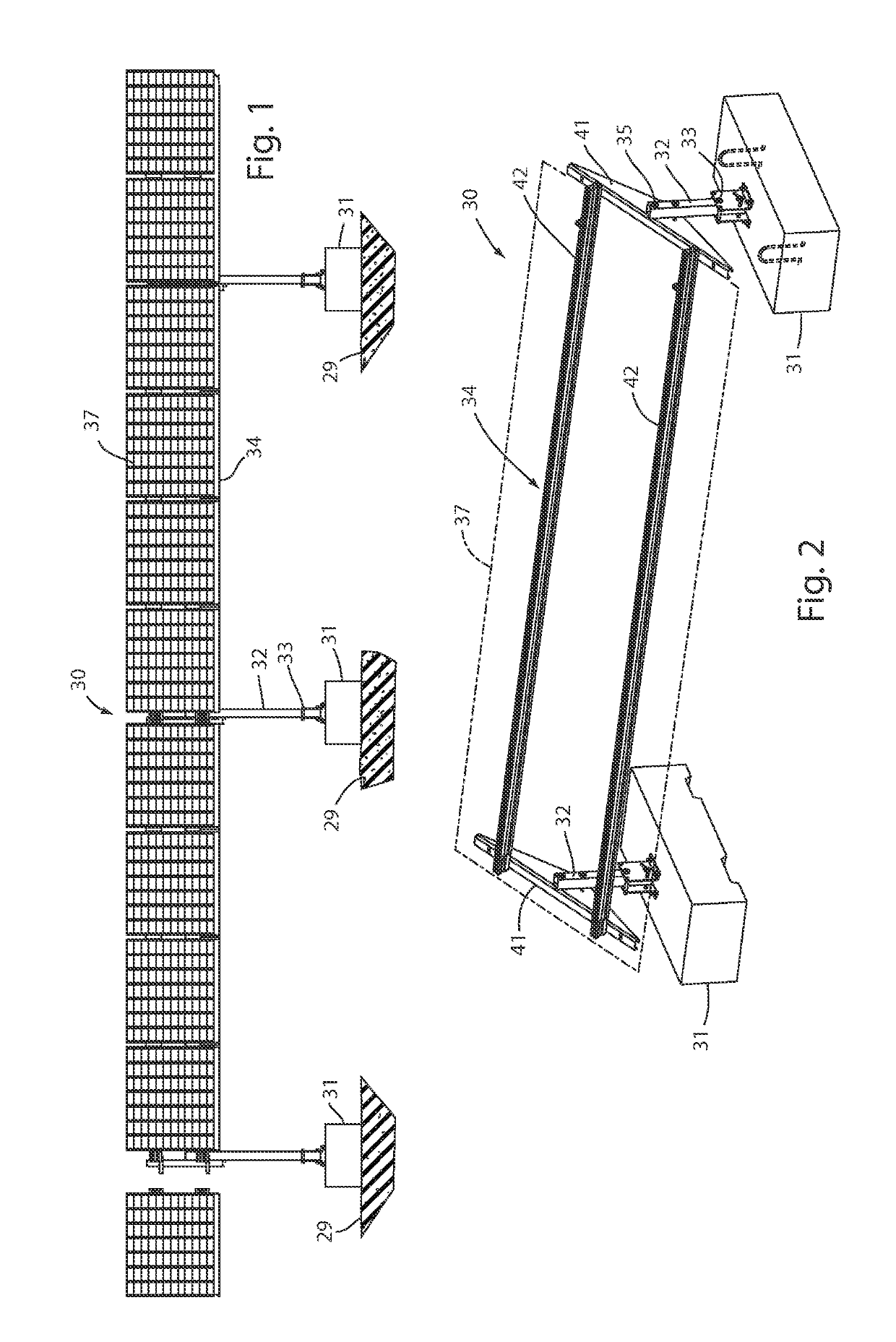
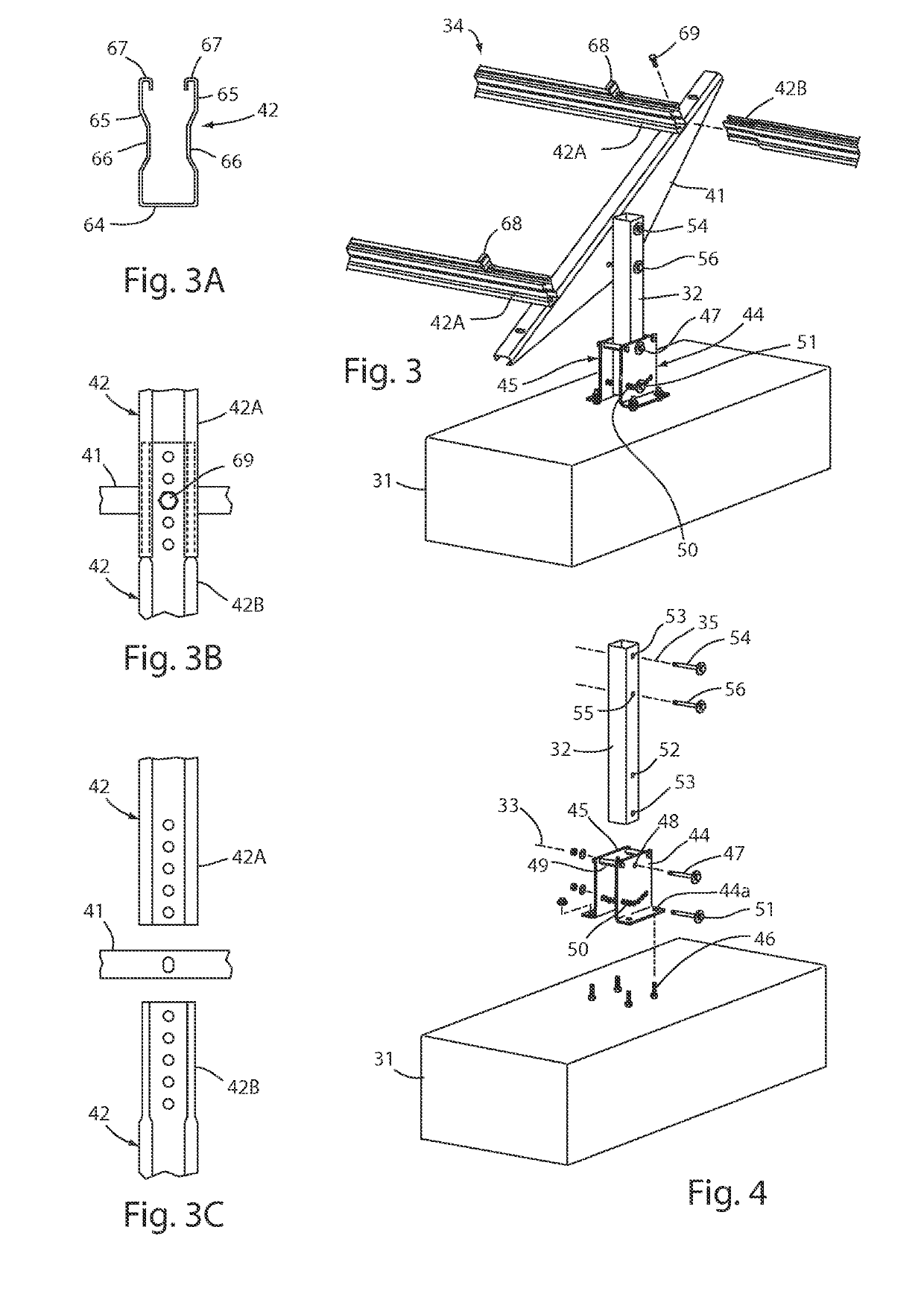
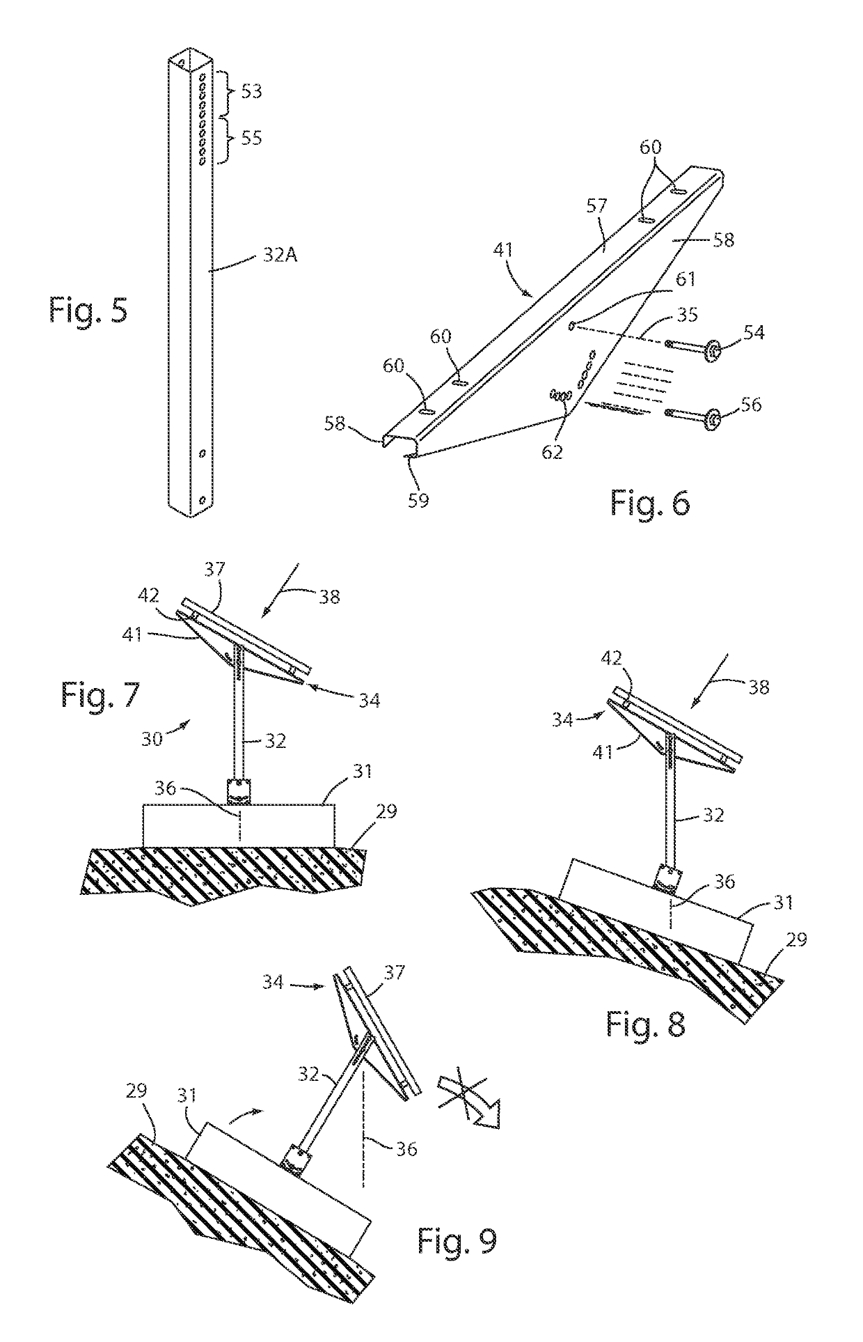
[0036]A solar panel mount system 30 (FIGS. 1-2) includes a plurality of a ballasted block support 31 resting on a ground surface 29, a post 32 pivoted to the block support 31 at a lower pivot 33, and a solar panel frame 34 pivoted to the post 32 at an upper pivot 35. The lower and upper pivots 33 and 35 locate a center of gravity (FIGS. 7-8) of the solar panel frame 34 and supported solar panels 37 ge...


PUM

PropertyMeasurementUnit
weightaaaaaaaaaa
thicknessaaaaaaaaaa
gravityaaaaaaaaaa

Abstract

A solar panel mount system includes a ballasted block support resting on a ground surface, a post pivoted to the block support at a lower pivot, and a solar panel frame pivoted to the post at an upper pivot with a center of gravity over the ballasted block support and facing a desired sunlight-receiving direction. The upper pivot is selected to be at a desired adjusted height. The frame includes a yoke supported at the upper pivot and support beams supporting a solar panel. A method of installation includes placing the ballasted block support on the ground, and attaching the remaining components at desired angles to locate a center of gravity of the solar panel frame over the ballasted block support, and fixing an angle of the solar panel frame at a desired sun-facing position. A related method includes interconnecting solar panel frames on posts in a generally straight row.

Description

[0001]This application claims benefit under 35 USC section 119(e) of a provisional application Ser. No. 61 / 698,649, filed Sep. 9, 2012, entitled SINGLE AND MULTI-AXIAL ARTICULATION IN BALLASTED PHOTOVOLTAIC MOUNTING SYSTEMS, the entire contents of which are incorporated herein by reference.BACKGROUND[0002]The present invention relates to ballasted mounting apparatus and systems for supporting a photovoltaic (solar panel) array at an optimal position to harvest solar energy from incident solar radiation, and more particularly relates to a ballasted mounting apparatus having advantages of mechanically simple components that are few in number and intuitive to assemble, low in cost to install, and low in cost of materials, yet are robust, highly adjustable, sufficiently rugged for use in difficult environments, and very flexible and well adapted for use in different environments with minimal site preparation.[0003]Solar systems are often installed on uneven or unfriendly terrain where l...

Claims


Application Information

Patent Timeline
Patent Type & Authority Patents(United States)
IPC IPC(8): F24S25/12F24S25/617H02S20/10H02S20/30H01L31/18F24S25/70F24S25/00
CPCH01L31/18F24S25/12F24S25/617F24S25/70H02S20/30H02S20/10Y10T29/49355F24S2025/019F24S2025/02Y02E10/47F24S25/65Y02E10/50
Inventor WOLTER, JAMESMATHIE, JEFFREY
Owner WOLTER JAMES
Why Eureka
Try Eureka