Device and method for guiding metal strips having wear bodies

a technology of wear body and guide rod, which is applied in the direction of web handling, transportation and packaging, manufacturing tools, etc., can solve the problems of affecting the service life of the guide rod, and the need to replace the guide rod, etc., so as to reduce the risk of damage, reduce the risk of wear and tear, and prolong the guide length

Active Publication Date: 2019-08-13
PRIMETALS TECH AUSTRIA GMBH
View PDF41 Cites 3 Cited by
  • Summary
  • Abstract
  • Description
  • Claims
  • Application Information

AI Technical Summary

Benefits of technology

[0035]In comparison with U.S. Pat. No. 2,818,954 which has guide disks which are disposed at an angle to the conveying direction, the device according to the invention, has a wear face which is substantially planar and parallel with the guide plane. This allows for a longer guide length for the metal strip. A comparatively lower bearing pressure is generated, which presents a lower risk of damage to an edge of the metal strip and therefore enhances the ability for thinner strips to be handled. On the other hand, there is less wear on the wear bodies, leading to increased service life or to a lower requirement replacements, and a replacement interval may be six times longer in practice.
[0036]As opposed to JP05161917, the apparatus hereof has rotating rollers, which assume defined rotary positions according to the invention. This leads to an improved guiding function on account of the metal strip cutting into the wear body and to improved distribution of wear across various regions. Therefore, comparatively thinner metal strips may be handled, for example.
[0037]The wear bodies are preferably replaceable, so that these components may be readily replaced if there is excessive wear. Replacement of the main body modules, or of parts of the main body modules, such as wear plates, for example, which in comparison is a more complex procedure, is more rarely required. This provides savings of effort and costs for maintaining the device for lateral guiding.
[0038]In one embodiment, a plurality of the wear bodies have a wear face, and those wear bodies are rotatable to a plurality of defined rotary positions. At least one of these wear bodies is rotatable independently of other wear bodies. As a result, the extent of wear on individual wear bodies may be considered when exposing new regions of the wear bodies, and rotating may be performed in an individual manner, as needed. This may further lower the effort for renewing worn-out wear bodies.
[0039]According to one embodiment, a plurality of wear bodies having a wear face are present, and which are rotatable to a plurality of defined rotary positions. At least one of these wear bodies is rotatable dependent with at least one other of these wear bodies. As a result, the extent of wear on groups of at least two wear bodies may be considered when exposing new regions of the body or the wear face, and such groups may be rotated depending on necessity. This may further lower the effort for renewing worn-out wear bodies.
[0040]A wear body is rotatable about a rotation axis. Once wear of a region of the wear face of the wear body exceeds an acceptable extent, the wear body may be rotated in a controlled manner about the rotation axis, to turn an as yet unspent region to face the edge of the metal strip to be worn by that edge. The requirement for replacing the wear face or the wear body, respectively, may be delayed by way of repeated controlled rotation, since new and as yet non-worn regions are turned to face the edge of the metal strip.

Problems solved by technology

The edges of the running metal strip on which the devices for lateral guiding act cause heavy wear on the wear strips (which are fastened to the guide rulers or to the run-in rulers, respectively) or on the wear faces of said wear strips, respectively.
Especially in the case of comparatively thin strips, the strip edges which are guided by way of high lateral forces cut into the wear strips along the entire length of the strip (which may be up to 2000 m in length) while creating sparks.
It is disadvantageous here that the guide rulers which are complex and expensive in manufacture eventually always have to be replaced.
Moreover, there is the risk that in the case of the gap between the roller table rollers and the guide ruler being modified, the gap may assume dimensions which may cause misguiding such as threading or jamming of the metal strip, respectively.
It is disadvantageous here, that there is a risk during threading the front end of a metal strip that above all in the case of thin strips the edges of the leading strip end may be skewered on the protruding regions and that the metal strip will thus be damaged.
New regions may be exposed to wear by rotating these guide disks.
Rolling off on such guide rollers reduces the wear thereof and does not allow continuous notches to be created.
However, when such rollers are used for lateral guiding of metal strips the risk of the edges of the latter being damaged by the guide rollers increases as the metal strips become thinner.
Employing such guide rulers is therefore only possible for metal strips of limited thickness.
Moreover, here too, edges of the leading strip end may be skewered on the protruding guide rollers.

Method used


Image

  • Device and method for guiding metal strips having wear bodies
  • Device and method for guiding metal strips having wear bodies
  • Device and method for guiding metal strips having wear bodies

Examples


Embodiment Construction

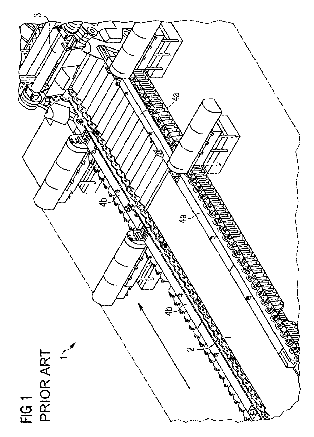
[0131]FIG. 1 schematically shows a conventional device 1 for laterally guiding a metal strip 2 running over a roller table, in a perspective view from above. The metal strip 2 runs in the direction of the arrow in the direction of a driver 3 of a coiling plant. Said metal strip is laterally guided by means of the run-in rulers 4a, 4b.

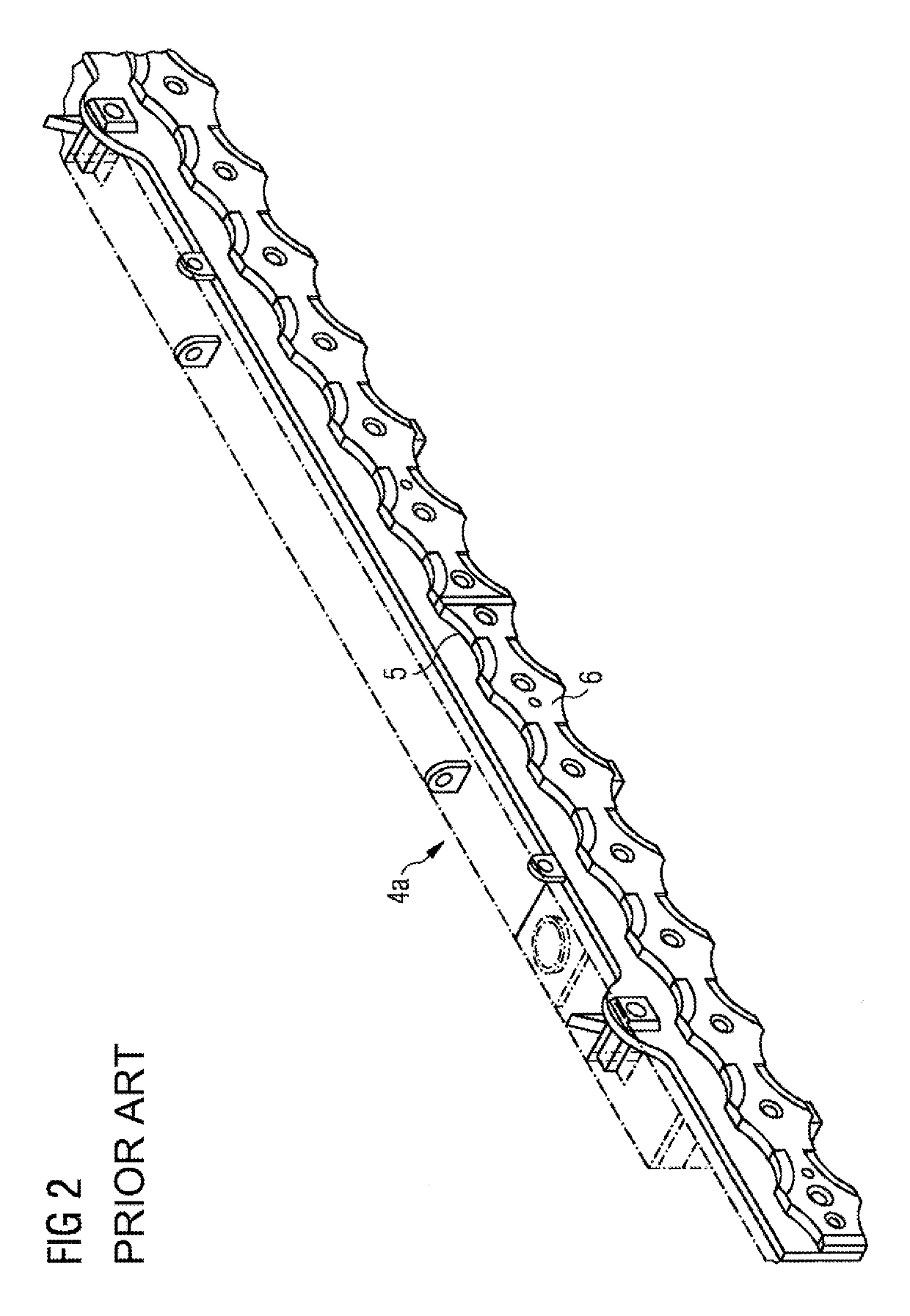
[0132]FIG. 2 shows part of a wear strip 5 of a run-in ruler 4a or 4b of a known device 1 of FIG. 1, for laterally guiding a metal strip running over a roller table. A metal strip is guided by means of the guide plane 6. The wear strip here is worn-out and needs to be replaced.

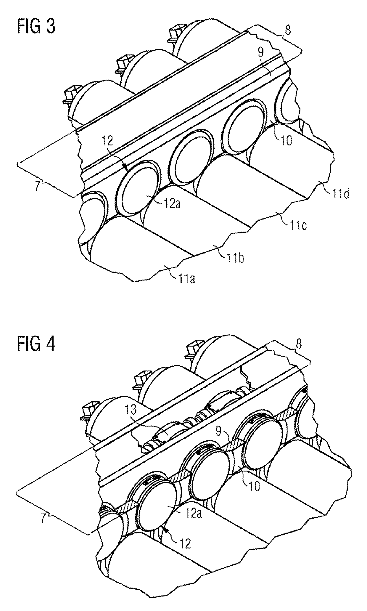
[0133]FIG. 3 shows a fragment of a device according to the invention for laterally guiding a metal strip running over a roller table as a metal-strip conveying device. Of the device, a main body module 7 comprised of a support body 8 carrying a wear plate 9 having a substantially vertical guide plane 10 is shown. Also illustrated are roller table rollers 11a, 11b, 11c, 11d. A wear...


PUM

PropertyMeasurementUnit
lengthaaaaaaaaaa
temperatureaaaaaaaaaa
thicknessesaaaaaaaaaa

Abstract

A device for lateral guidance (1) of a metal strip (2) moving on a metal belt conveying device, including at least one base body module (7) includes an essentially vertical guiding plane (10), at least one wear body (12) having a wear surface (12a) can be rotated into several defined rotational positions in a controlled manner. The wear surface (12a) is substantially planar, and in all of its defined rotational positions, is parallel to the guiding plane (10). Further, a method for lateral guidance of metal strips (2) moving on a metal belt conveying device includes, after a first metal strip has passed through the metal belt conveying device, and prior to a second metal strip entering the metal belt conveying device, the wear body (12) is rotated from a first to a second defined rotational position in a controlled manner, wherein in all defined rotational positions, the wear surface (12a) is parallel to the guiding plane (10).

Description

CROSS-REFERENCE TO RELATED APPLICATIONS[0001]The present application is a 35 U.S.C. §§ 371 national phase conversion of PCT / EP2014 / 068929, filed Sep. 5, 2014, which claims priority of European Patent Application No. 13186131.2, filed Sep. 26, 2013, the contents of which are incorporated by reference herein. The PCT International Application was published in the German language.TECHNICAL FIELD[0002]The present invention relates to a device for laterally guiding a metal strip running over a metal-strip conveying device, the device comprising at least one main body module having a substantially vertical guide plane.PRIOR ART[0003]During their manufacture, metal strips are directed by means of metal-strip conveying devices, for example by roller tables, to processing machines, for example coiling machines, where the metal strips are wound up. It is necessary here for the metal strips to be subjected to lateral guiding. This is particularly necessary prior to winding up, to as far as pos...

Claims


Application Information

Patent Timeline
Patent Type & Authority Patents(United States)
IPC IPC(8): B21B1/22B21B39/14B65H23/032
CPCB21B39/14B65H23/032B21B1/22B65H2701/173B21B39/18B21B2267/24
Inventor FRAUENHUBER, KLAUSGRABNER, WALTERMOSER, FRIEDRICHSCHIEFER, JUERGEN
Owner PRIMETALS TECH AUSTRIA GMBH
Why Eureka
Try Eureka