
Adjustable spacing comb, adjustment drive and hair cutting appliance

a technology of adjustment drive and adjustable spacing comb, which is applied in the direction of metal working apparatus, etc., can solve the problems of cumbersome user operation coarse positioning of adjustable spacing comb in the provided adjustment range, and affecting the operation of motorized adjustment combs, etc., to reduce the tendency of soiling and dirt deposits, and facilitate the formation of devices in waterproof conditions.

Active Publication Date: 2019-08-13
KONINKLJIJKE PHILIPS NV
View PDF18 Cites 3 Cited by
  • Summary
  • Abstract
  • Description
  • Claims
  • Application Information

AI Technical Summary

Benefits of technology

[0013]It is an object of the present invention to provide a hair cutting appliance, an adjustable spacing comb for a hair cutting appliance, and an adjustment drive for such an adjustable spacing comb that may overcome at least some of the above-mentioned problems. In particular, it is an object to provide an adjustment drive for an adjustable spacing comb that may ensure simplified operability and, more preferably, extended input options for a user. It would be further beneficial to seek for improvements in adjustment speed and adjustment precision and accuracy. It would be further advantageous to provide a corresponding method for operating an adjustable spacing comb.
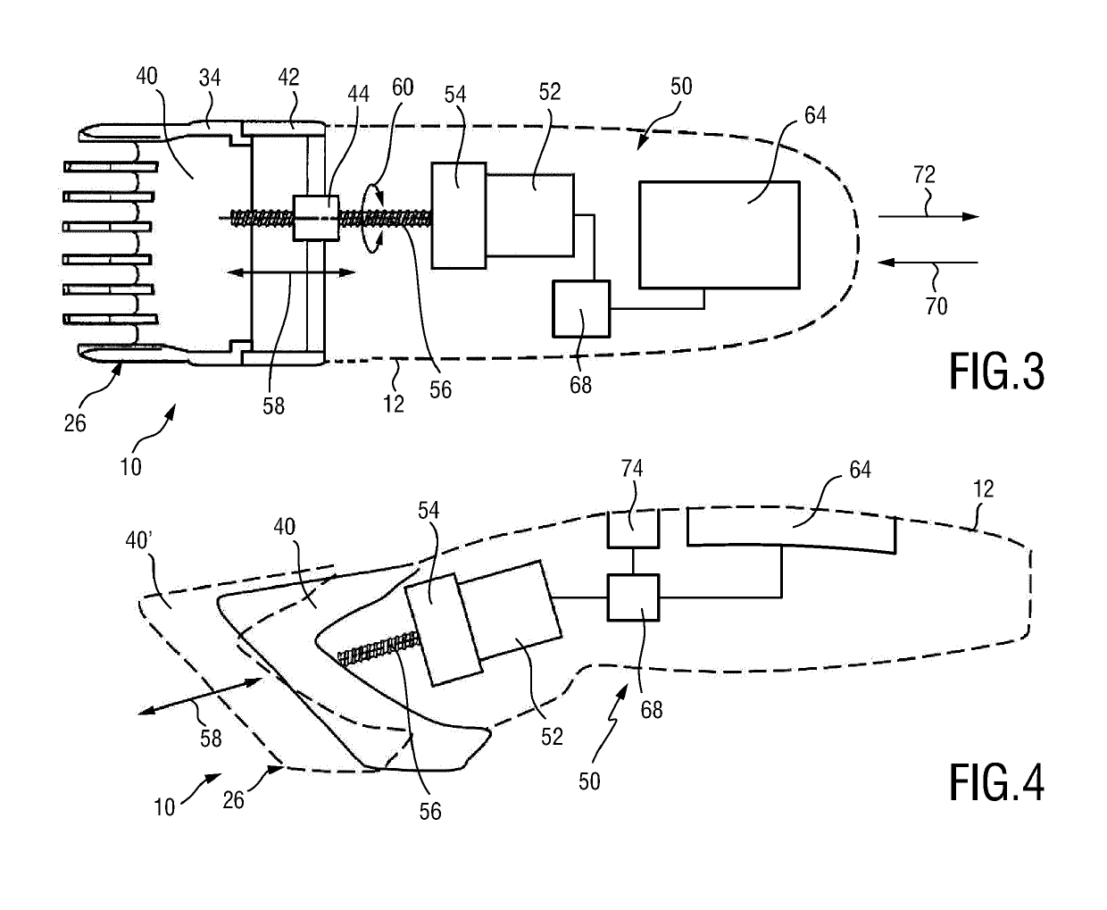
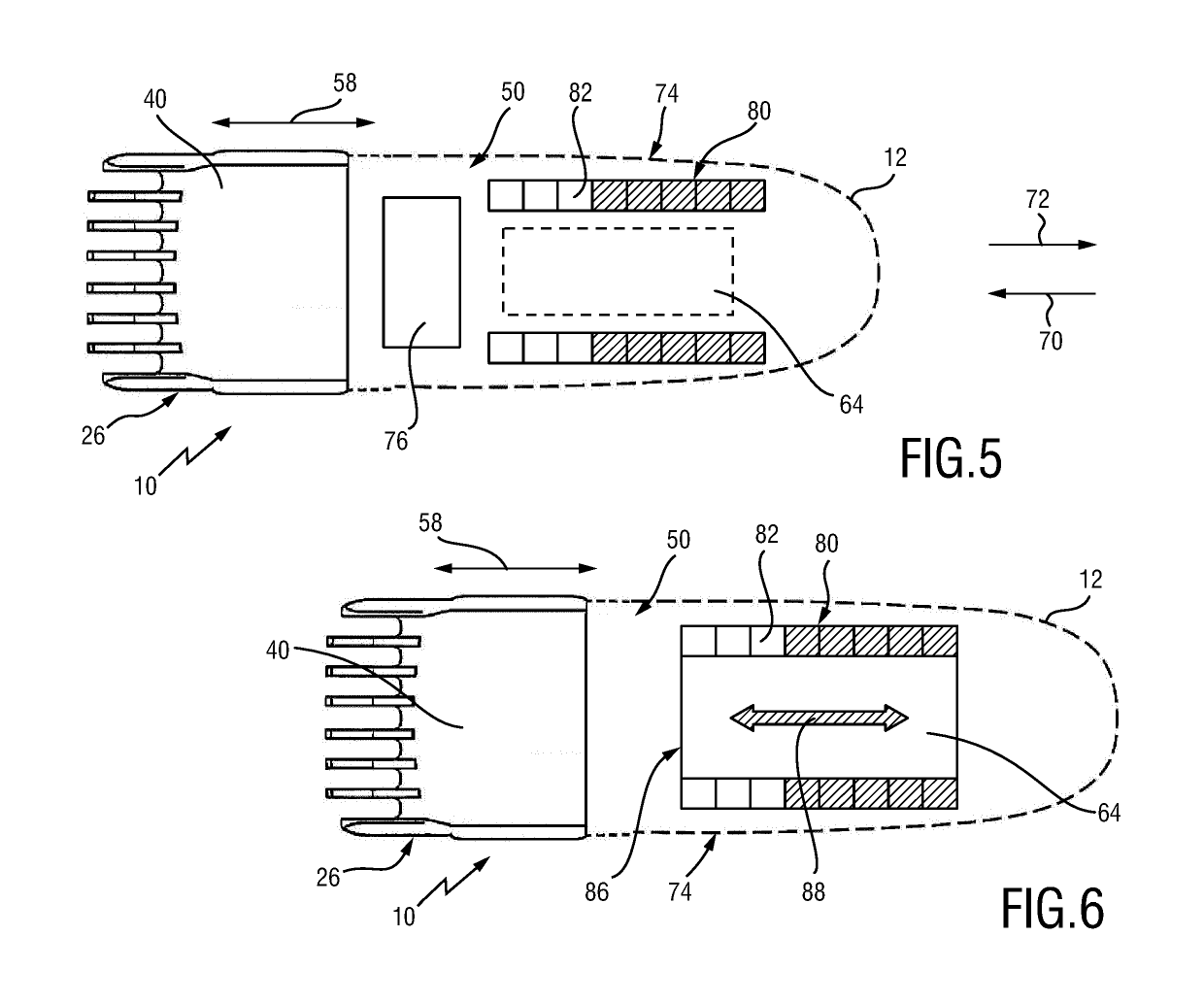
[0019]This aspect is based on the insight that the sensor element—which is touch sensitive sensor element which may also involve that the sensor element is arranged as a proximity sensitive sensor element—may enable user input actions which may induce both precise positioning and quick positioning of the movable comb portion. This can be achieved since the sensor element is capable of detecting multi-faceted user inputs. On the one hand side, the user may operate the sensor element slowly and by small increments (strokes). This may enable a precise positioning of the movable comb portion. On the other hand, the user may operate the sensor element quickly and by large increments (strokes). Operating the sensor element may typically comprises applying strokes or swipe movements to a sensing surface of the sensor element or, at least, in the proximity of the sensor element. Consequently, the sensor element may be configured and / or operated to detect dynamic properties and to exhibit “simulated” inertia properties. By applying quick and considerably long strokes to the sensor element, the movable comb portion may be moved by a considerably long distance. Conversely, the user may slightly and slowly drag over the sensor element so as to move the movable comb portion by considerably small increments. The sensor element may be arranged as a touch sensitive surface (touchpad) and / or a touchscreen.
[0025]The adjustment drive in accordance with the above aspect may have the further advantage that a single sensor element may be used for extending and retracting the movable comb portion. Basically, the sensor element may detect opposite input stroke directions. Consequently, the input motion direction may be “translated” into an extending or a retracting motion of the movable comb portion.
[0035]Consequently, the control unit is operable to either “amplify” (or gear up) detected user inputs into a large comb adjustment response or to “gear down” detected user inputs into a small comb adjustment response. Consequently, slow user input movement may result in precise incremental step output while fast user input movement may result in fast output at relatively large increments.
[0036]Generally, the present disclosure makes use of the idea that the activation impulse applied by the user to the sensor element and a corresponding data processing activity carried out by the control unit can be (physically) decoupled from each other such that a respective operation mode detection algorithm may be interposed between the user input impulse and the determination of the corresponding actuator operation signal. In other words, the operation mode detection algorithm can detect or, rather, anticipate whether fast response or slow response is desired by the user. This may further result in a quickly moving movable comb portion towards longer (absolute and / or relative) length settings, and a slowly and precisely moving movable comb portion in a shorter (absolute and / or relative) length setting range.
[0048]In one embodiment of the hair cutting appliance, the sensor element is inconspicuously integrated in the housing portion. This may involve that the sensor element is hidden in the housing portion. Preferably, the sensor element, particularly a touch-sensitive or proximity-sensitive foil thereof, is covered by a wall of the housing portion. This may be advantageous since in this way an integrally shaped housing portion may be provided that exhibits a reduced tendency for soiling and dirt deposits. Furthermore, forming the device in a waterproof-manner can be facilitated. However, as indicated above, alternatively or in addition, the hair cutting appliance may be fitted with a touchscreen that may be utilized for the detection of multi-faceted user inputs and, at least in some embodiments, for providing user feedback, particularly user guidance.

Problems solved by technology

However, operating a motorized adjustment comb frequently has proven to be afflicted with several drawbacks.
It is often cumbersome for the user to operate the adjustable spacing comb in a precise and accurate manner since typically rather conventional control elements are provided, for instance push buttons, control levers etc.
Consequently, coarsely positioning the adjustable spacing comb in the provided adjustment range (which may include covering considerably long distances in the adjustment range) may be experienced as time-consuming.
Furthermore, fine adjustment of the adjustable spacing comb may be difficult since conventional control elements typically require considerably large minimum increments of the adjustment motion, as indicated above.
Due to the above-mentioned lack of operating and adjusting efficiency of conventional adjustable spacing comb arrangements, operating the hair cutting appliance may be further complicated.

Method used


Image

  • Adjustable spacing comb, adjustment drive and hair cutting appliance
  • Adjustable spacing comb, adjustment drive and hair cutting appliance
  • Adjustable spacing comb, adjustment drive and hair cutting appliance

Examples


Embodiment Construction

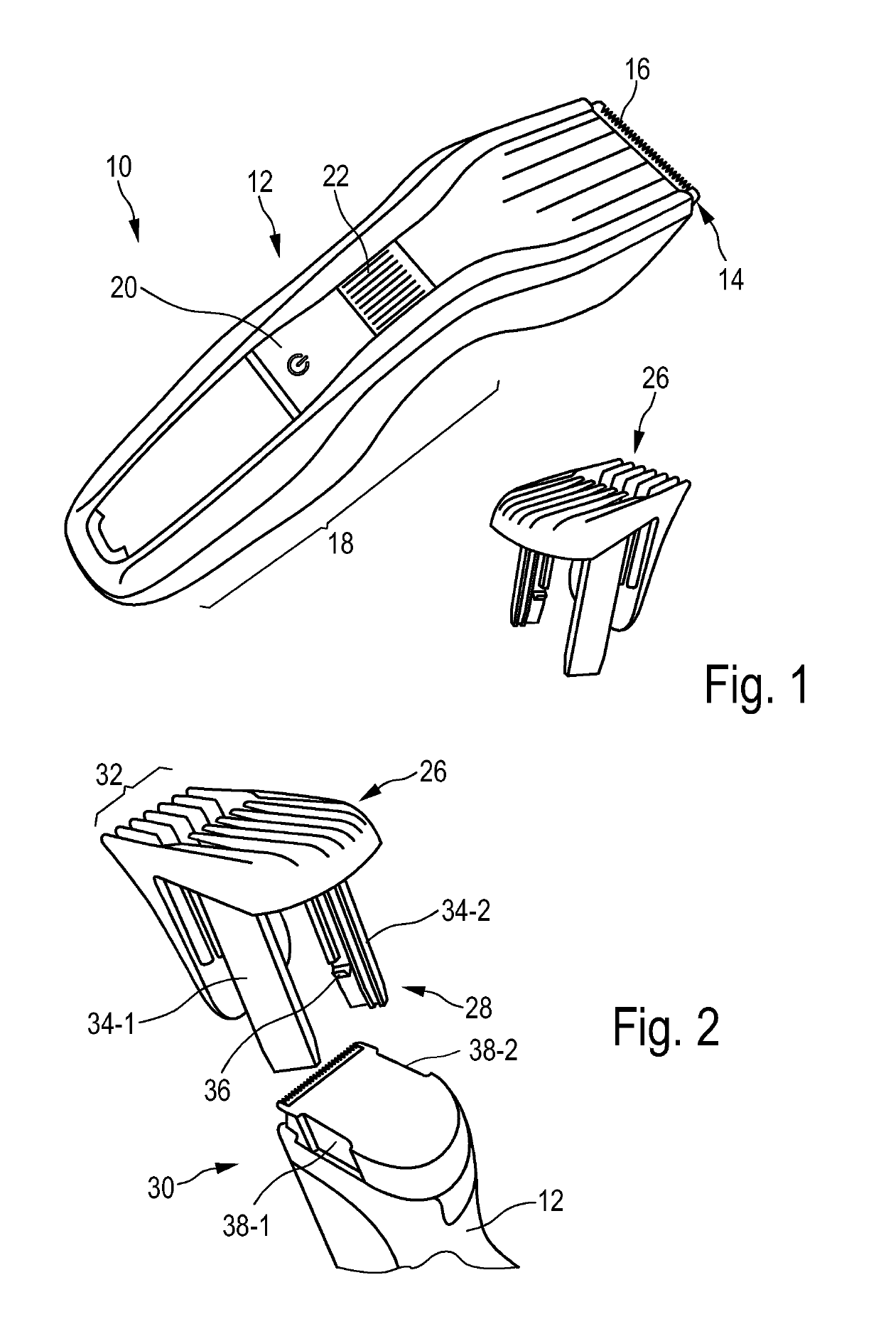
[0068]FIG. 1 shows a schematic perspective view of a hair cutting appliance 10, particularly an electrically-operated hair cutting appliance 10. The hair cutting appliance 10 may also be referred to as hair clipper or hair trimmer. The hair cutting appliance 10 may comprise a housing or housing portion 12 having a generally elongated shape. At a first end thereof, a cutting unit 14 may be provided. The cutting unit 14 may comprise a blade set 16. The blade set 16 may comprise a movable blade and a stationary blade that may be moved with respect to each other to cut hair. At a second end of the housing portion 12, a handle or grip portion 18 may be provided. A user may grasp or grab the housing at the grip portion 18.

[0069]The hair cutting appliance 10 may further comprise operator controls. For instance, an on-off switch or button 20 may be provided. Furthermore, a length adjustment control 22 may be provided at the housing 12 of the hair cutting appliance 10. The length adjustment ...


PUM


Abstract

An adjustment drive is provided for an adjustable spacing comb for a hair cutting appliance. The adjustment drive includes an actuator, a sensor element and a control unit. The actuator actuates a movable comb portion of the adjustable spacing comb with respect to a blade set of the hair cutting appliance. The sensor element detects multi-faceted user inputs applied to the sensor element by a user and to output a user input signal that is derived from the multi-faceted user inputs. The actuator is operated on the basis of the user input signal. The control unit is coupled to the actuator and to the sensor element, and converts the user input signal into an actuator operating signal. The multi-faceted user inputs include detected user input speed of an input stroke by the user.

Description

[0001]This application is the U.S. National Phase application under 35 U.S.C. § 371 of International Application No. PCT / EP2015 / 071027, filed on Sep. 15, 2015, which claims the benefit of International Application No. 14185364.8 filed on Sep. 18, 2014. These applications are hereby incorporated by reference herein.FIELD OF THE INVENTION[0002]The present disclosure relates to an adjustment drive for an adjustable spacing comb for a hair cutting appliance, wherein the adjustment drive comprises an actuator that is configured for actuating a movable comb portion of the adjustable spacing comb with respect to a blade set of the hair cutting appliance, and a drivetrain for coupling the actuator and the movable comb portion, wherein the drivetrain comprises a reduction gear unit. The present invention further relates to an adjustable spacing comb comprising such an adjustment drive and to a hair cutting appliance that comprises such an adjustable spacing comb.BACKGROUND OF THE INVENTION[0...

Claims


Application Information

Patent Timeline
Patent Type & Authority Patents(United States)
IPC IPC(8): B26B19/20B26B19/00B26B19/38
CPCB26B19/20B26B19/388B26B19/3886B26B19/3813B26B19/00
Inventor DARWINKEL, GEERT-JANBRAAKSMA, ALLEZANDSTEEG, CORNELIS JOHANNES
Owner KONINKLJIJKE PHILIPS NV
Learn More