
Curtain wall frame

a curtain wall and frame technology, applied in the field of curtain walls, can solve the problems of increased production costs, increased production costs, and insufficient support structures for typical curtain walls, and achieve the effect of increasing the moment of inertia valu

Inactive Publication Date: 2019-08-13
PROFAL LTD
View PDF32 Cites 0 Cited by
  • Summary
  • Abstract
  • Description
  • Claims
  • Application Information

AI Technical Summary

Benefits of technology

This invention is a support member for curtain walls that can handle large loads with minimal deformation. It is made up of two parts that are connected in compression, which allows for longer support members with higher moments of inertia and stiffness values. The use of longer support members eliminates the need for larger flanges, resulting in a lighter and more cost-effective design. The modularity of this support member also makes it easier to import, transport, and manufacture. Additionally, the attachment means holds the two parts in compression, preventing instability and deformation issues.

Problems solved by technology

A typical curtain wall size corresponds with the story height of most office buildings, but when constructing a lobby, penthouse, hall or other structure with high ceilings, the support structures used for typical height curtain walls no longer suffice.
There are many unique challenges for providing such a unique support member.
For this purpose, replacing the aluminum material is often attempted in the industry but it also introduces many disadvantages:(a) Aluminum is a very abundant, easy to produce, and theoretically 100% recyclable material.
Replacing aluminum would involve higher production costs resulting from the usage of more valuable and difficult materials;(b) Aluminum is easily extruded using well-known processes, to produce linear forms of nearly unlimited cross-section design.(c) Aluminum is a durable and visually appealing material.
Replacing aluminum would most often result in a coarse and un-esthetic visual look to the curtain wall.
However in the case of extruded members a practical limit of around 30 cm maximum member thickness is reached, since aluminum extruders generally use dies of this diameter and cannot produce items of greater transverse dimensions.
While larger dies can be constructed, machines adapted to use them are not generally available and hence this size represents a practical limit in terms of cost of production.
Furthermore, elongating the web, instead of increasing the web thickness (which is not an effective means for increasing the moment of inertia of the member), would create a thin proportioned support member, ultimately degrading the support member's stability by introducing a ‘wobbling’ effect to the web which will lead to further deformation.
Nevertheless, designs following this standard design doctrine have practical drawbacks and limitations, for instance namely that unreasonable flange thickness, produces high material requirements and ultimately results in high weight and high materials bill.
Furthermore, due to the 30 cm common extruder limit increasing flange thickness too much comes at the expense of web length, resulting in an inefficient and ineffective disproportionate support member.
Additionally, standard extruders have a practical limit of approximately 130 kg extrusion mass.
Due to the extruder mass limit, the support member will fall short of the required total length.
There is a further practical limitation involving the length and the weight of the extrusions.
The transportation and handling of regular curtain wall support members, is already a difficult task and it becomes even more severe, with extra-large support members which are only available through import and naval transportation from countries with suitable massive extruders.
Needless to say that these logistical obstacles greatly increase costs and also prolong delivery times.

Method used


Image

  • Curtain wall frame
  • Curtain wall frame
  • Curtain wall frame

Examples


Embodiment Construction

[0052]The present invention will be understood from the following detailed description of preferred embodiments, which are meant to be descriptive and not limiting. For the sake of brevity, some well-known features, methods, systems, procedures, components, circuits, and so on, are not described in detail.

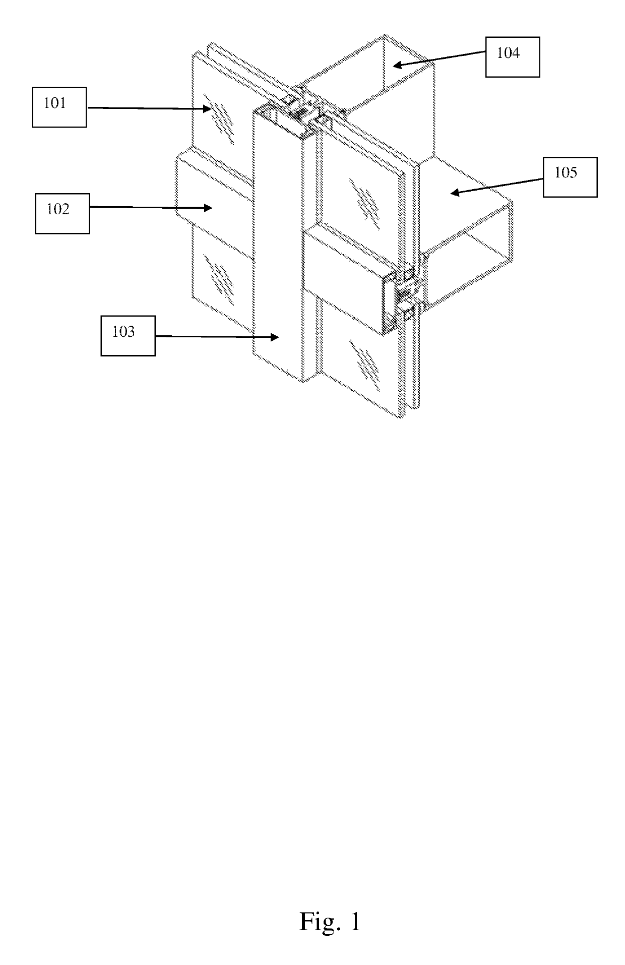
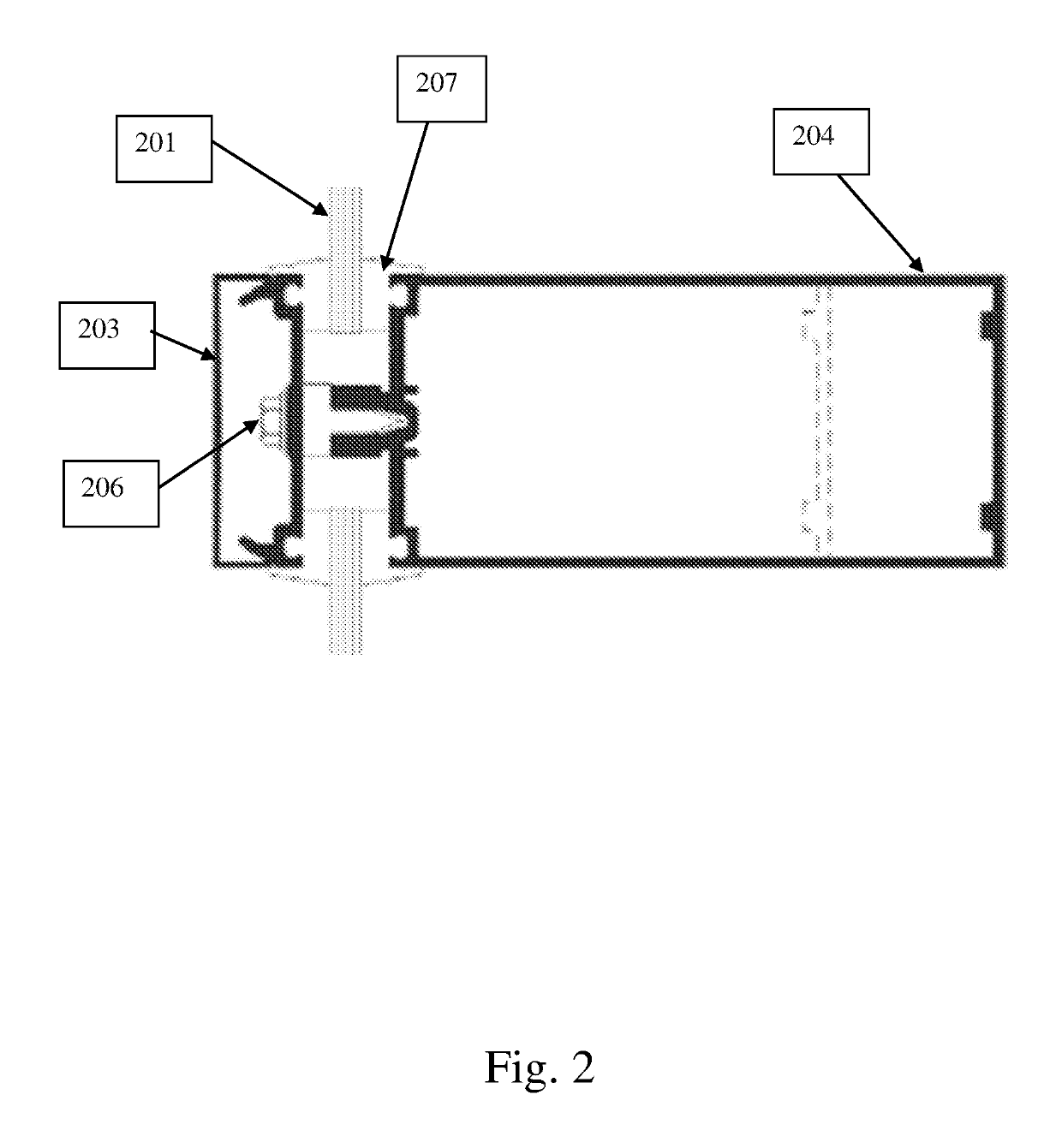
[0053]A standard support is shown in FIGS. 1,2.

[0054]Here the glass panes 101 are shown, held in place by horizontal transom and vertical mullion extruded rear support members 104,105 respectively. The panes are held in tension between these rear members 104,105 and holding caps 102,103 which are generally attached to the rear members by means of screws or the like concealed within the members.

[0055]FIG. 2 shows the same support members in section. Here the bolt 206 holding the rear support 204 to the holding cap 203 is visible. This bolt holds the rear support and the holding cap together and thereby compresses the window section 201 between flexible abutting members 207 which may...


PUM


Abstract

The invention comprises a two-part support member for curtain walls capable of withstanding the extreme loads required for extra-large walls with minimal deformation comprising two independently extrudable components, each of which may be produced on standard extruders and attachment means that holds the extrudable components together. The sections fit together in such a way that inevitable deformations that occur during production are taken into account and corrected for. Due to the hitherto unattainable stiffness values that this combination of components may reach, extra-large curtain walls mounting and supporting is achieved that was otherwise unattainable. The cross sectional area of the sections is relatively small allowing for lightweight members to be extruded that use a minimum of material.

Description

CROSS-REFERENCE TO RELATED PATENT APPLICATIONS[0001]This application is a National Phase of PCT Patent Application No. PCT / IL2016 / 050943 having International filing date of Aug. 29, 2016, which claims the benefit of priority of IL 242894, filed Dec. 2, 2015. The contents of the above applications are all incorporated by reference as if fully set forth herein in their entirety.FIELD OF THE INVENTION[0002]The present invention relates to the field of curtain walls.BACKGROUND OF THE INVENTION[0003]Curtain walls are non-structural walls usually on the outside of a building. We use the term ‘nonstructural’ in the sense that these walls does not carry any load from the building other than their own. Due to this freedom from loading constraints, curtain walls can be made of lightweight materials such as glass, plaster, MDF, or the like instead of iron or concrete as most load-bearing walls are.[0004]In the case of an outer curtain wall, the wall does have to resist wind loads and transfer ...

Claims


Application Information

Patent Timeline
Patent Type & Authority Patents(United States)
IPC IPC(8): E04B2/96
CPCE04B2/967
Inventor LEVIN, YAIR
Owner PROFAL LTD
Learn More