Inline scrubber with dual water system

a scrubber and water system technology, applied in the field of scrubbers, can solve the problems of reducing the space available for scrubbers and scrubbers, affecting the cleaning effect, and affecting the cleaning effect, and achieve the effect of less space demanding

Active Publication Date: 2019-08-13
WARTSILA MOSS AS
View PDF19 Cites 0 Cited by
  • Summary
  • Abstract
  • Description
  • Claims
  • Application Information

AI Technical Summary

Benefits of technology

[0017]An advantage of the invention is that the wet scrubber according to the invention will treat exhaust gas in a marine vessel minimizing the problems of prior art. The scrubber is an efficient two or more-stage scrubbing system and is arranged to utilize the benefits of more scrubbing liquid types in one scrubber body, is less space demanding and may have a variety of alternatives for use depending on the surrounding environment. The basic idea of the invention is the inline system with two or more separate scrubbing liquid systems, i.e. in one and the same unit.
[0023]collecting the second scrubbing liquid, after being in contact with the gas in the one or more liquid collectors and lead into the second circuit liquid outlets in the lower part of the second scrubbing section of the extended body, preventing the second scrubbing liquid mixing into the first scrubbing liquid,

Problems solved by technology

Flue gas from combustion sources, for instance motors, often contains pollutive matter.
Such designs often becomes space demanding.
Onshore the space is necessarily not as important but if the scrubber will be used for instance onboard a ship the available space for the scrubber and the scrubbing arrangement will be limited.
Especially the available space will be limited if a scrubber is to be mounted to satisfy the severe limits for pollution from the exhaust gas onboard an existing ship.
Onboard a passenger ship the space will already be utilized to the maximum and available space for later installation will be limited and costly.
A limitation for size reduction is that when the scrubber size is reduced, the flue gas speed will rise and the pressure drop over a standard packed scrubber will reach a maximum limit.

Method used


Image

  • Inline scrubber with dual water system
  • Inline scrubber with dual water system
  • Inline scrubber with dual water system

Examples


Embodiment Construction

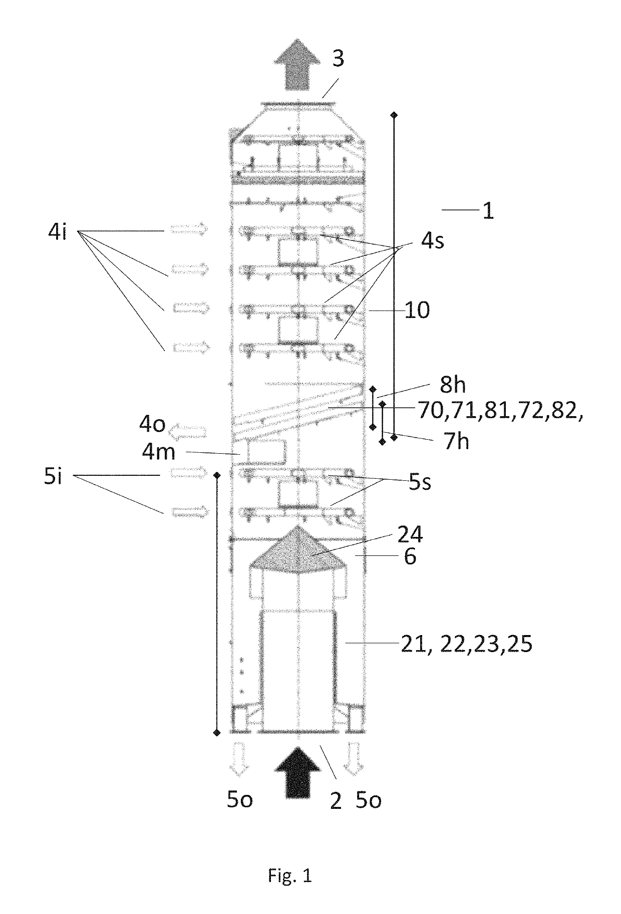
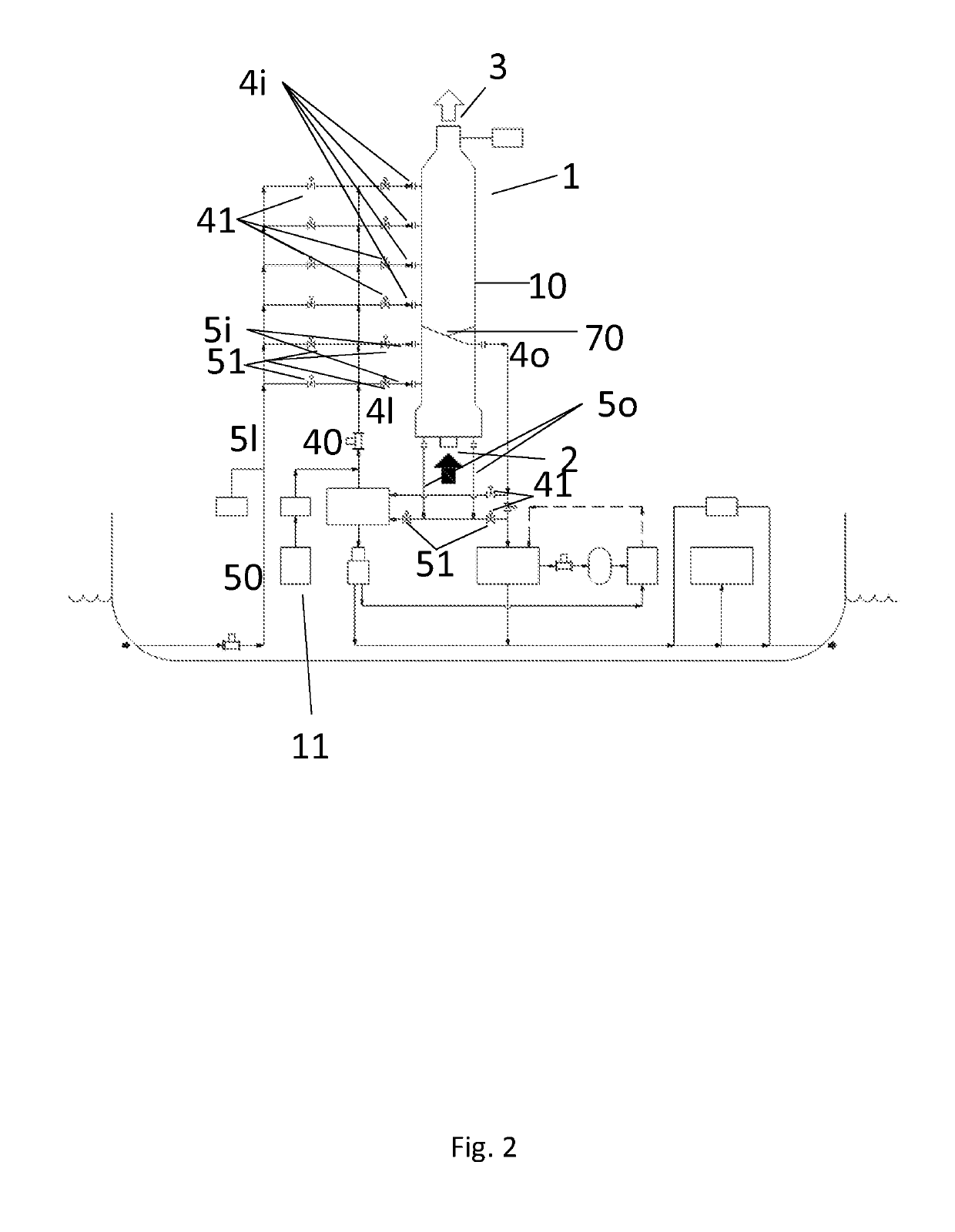
[0032]The present invention relates to an in-line dual water scrubber for gas cleaning, a scrubbing system and a method for exhaust gas cleaning onboard a vessel.

[0033]The invention will in the following be described and embodiments of the invention will be explained with reference to the accompanying figures. The present invention is an in-line dual water scrubber (1) for gas cleaning onboard a vessel and comprising a vertical extended body (10), a gas inlet (2), a gas outlet (3),[0034]the gas inlet (2) is underlying in the lower section of the extended body (10) and the gas outlet (3) is overlying in the upper section of the extended body (10),

a first underlying scrubbing section (5) comprising

one or more first circuit liquid inlets (5i),

one or more first scrubbing liquid spray means (5s)

one or more first circuit liquid outlets (5o), for a first scrubbing liquid (5l),

a second scrubbing section (4) in upper section of the extended body (10), comprising

one or more second circuit liq...


PUM

PropertyMeasurementUnit
buffering capacityaaaaaaaaaa
velocityaaaaaaaaaa
pressureaaaaaaaaaa

Abstract

A method for dual water scrubbing and an in-line dual water scrubber for gas cleaning onboard a vessel are disclosed. The in-line dual water scrubber includes a vertical extended body, a gas inlet, and a gas outlet. The gas inlet is underlying in the lower section of the extended body and the gas outlet is overlying in the upper section of the extended body. A first underlying scrubbing section, and a second scrubbing section in an upper section of the extended body are provided. One or more liquid collectors are arranged above one or more first scrubbing liquid sprayers. The liquid collector is arranged for collecting one or more second scrubbing liquid and for flow through of a vertical upwards flowing gas-flow from the inlet to the outlet.

Description

FIELD OF THE INVENTION[0001]The present invention relates to the technical field of wet scrubbing of exhaust gas. The invention relates to an apparatus, a scrubber, and a method for removing impurities, such as sulphur from a gas flow, preferably flue gas from a diesel or oil driven motor in a marine vessel, utilizing a dual water scrubbing system.BACKGROUND ART[0002]Flue gas from combustion sources, for instance motors, often contains pollutive matter. Such contaminants may be removed in a cleaning process. Such a cleaning process may be a scrubber. Scrubbers for cleaning flue gases may broadly be divided into two types, so called wet scrubber and dry scrubber. The main purpose for the scrubber is to remove or neutralize sulphur components from the flue gas, especially sulphur oxide. In addition one may often see that, for a wet scrubber, this will remove particulate matter as well, such as heavy metal, PAH (poly aromatic hydrocarbons), soot and sulphur bonded particles which may b...

Claims


Application Information

Patent Timeline
Patent Type & Authority Patents(United States)
IPC IPC(8): B01D45/00B01D53/14F01N3/04B01D47/06F01N13/00
CPCF01N3/04B01D47/06F01N13/0093F01N13/0097Y02T10/20B01D2247/04F01N2490/08F01N2590/02B01D2221/08B01D53/48B01D53/92Y02T10/12
Inventor GANNEFORS, JAN GUNNARCLAUSEN, PER
Owner WARTSILA MOSS AS
Why Eureka
Try Eureka