
Fastening device for an NMR probe having a quick-release fastener

a technology of nmr probe and fastening device, which is applied in the direction of geological measurements, nuclear magnetic resonance analysis, reradiation, etc., can solve the problems of inconvenient use, fixed connection, and inability to adapt to later position changes, so as to reduce material costs and manufacturing costs, and reduce the quality of nmr measurements

Active Publication Date: 2019-08-13
BRUKER SWITZERLAND AG
View PDF7 Cites 4 Cited by
  • Summary
  • Abstract
  • Description
  • Claims
  • Application Information

AI Technical Summary

Benefits of technology

The patent text describes techniques that modify a fastening device of a specific type to prevent discomfort or interference with NMR measurements. These techniques involve simple modifications that reduce the cost and manufacturing outlay of the NMR probe without compromising its quality or lifespan. The text also explains how these modifications enable quick changes to the NMR probe without reducing its service life.

Problems solved by technology

This is very inconvenient for the user, since the user typically crawls under the magnet in order to mount the probe and works kneeling down.
In addition, the relatively small screws are generally inconvenient due to the mounting position of the probe on the magnet and can normally be tightened only using a special screwdriver.
When the fastening screws are tightened, the connection is fixed and can no longer be adapted to later position changes, which may be caused by temperature changes, for example.
These position changes may cause mechanical backlash or unacceptable axial tension between the probe and the retention system.
After this maximum force has been overcome, the system relaxes and the probe may be mounted to the shim system of the NMR apparatus with an undefined force until a backlash arises that is possibly outside of acceptable tolerances.
However, the user may not be able to control the force that is set in the process.
In addition, the known quick-release fasteners of “wide bore probes generally provide no form of locking against inadvertent opening.
However, “standard bore” probes may require the positive locking feature due to safety considerations and marketing considerations.

Method used


Image

  • Fastening device for an NMR probe having a quick-release fastener
  • Fastening device for an NMR probe having a quick-release fastener
  • Fastening device for an NMR probe having a quick-release fastener

Examples


Embodiment Construction

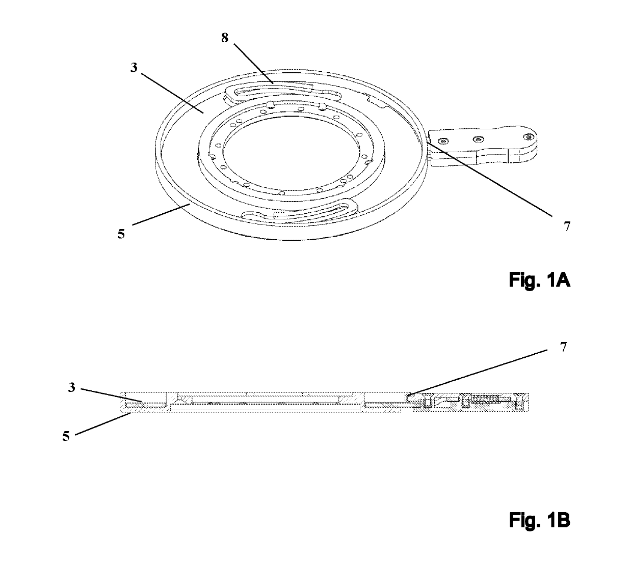
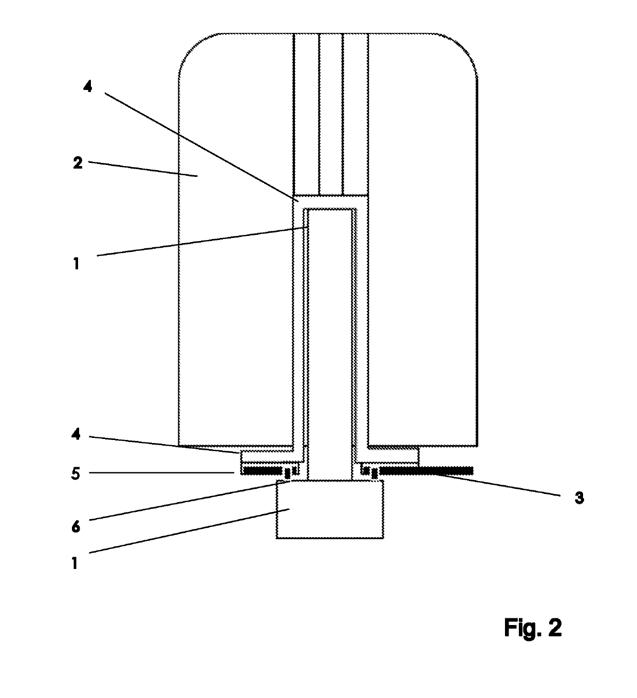
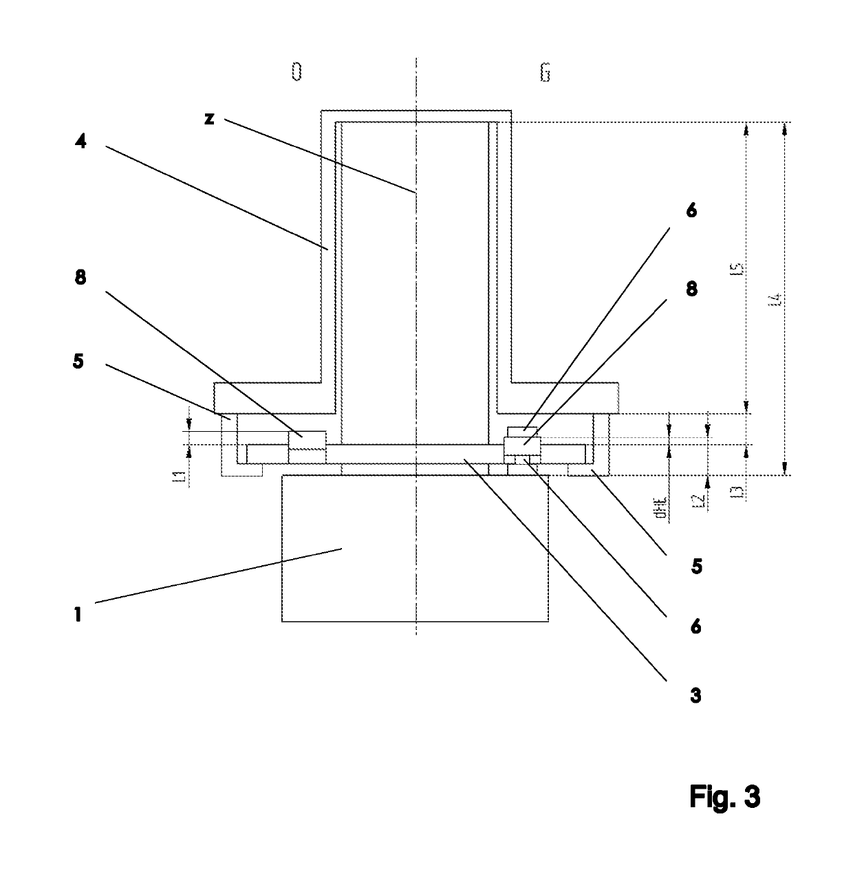
[0039]In general, the techniques described herein relate to a modified fastening device for releasably fastening an NMR probe 1 to an NMR magnet 2. The main axis of the NMR magnet 2 extends in parallel with a z-direction. To fasten the NMR probe 1 to the NMR magnet 2, a discoid insert 3 is pushed from below against a retention system 4 that is rigidly connected to the lower face of the NMR magnet 2. The NMR probe 1 is pushed against the lower face of the insert 3 that is remote from the retention system 4 until the upper end of the probe 1 comes into contact with the upper end of the retention system 4. Rotating the insert 3 about its disc axis (e.g., in parallel with the z-direction) establishes a rigid mechanical connection between the probe 1 and the insert 3 and between the insert 3 and the retention system 4. The discoid insert 3 is designed to establish a form-fitting and variable-force connection between the probe 1 and the retention system 4, using a spring element 8.

[0040]I...


PUM


Abstract

A fastening system for attaching an NMR probe to an NMR magnet includes a discoid insert and a retention system that is rigidly connected to the magnet and on which the insert can be mounted. A form-fitting, variable-force connection is established between the NMR probe and the retention system using a spring element. The probe attaches to the insert by a plurality of integral, rigid retaining elements that are of an invariable fixed length. The spring element and the retaining elements are designed geometrically such that in a first, opened state the connection between the insert and the retaining elements has a mechanical backlash between 0.5 mm and 5 mm when the spring element is relaxed. In a second, closed state the connection between the insert and the retaining elements has no mechanical backlash when the spring element is under mechanical tension.

Description

CROSS REFERENCE TO RELATED APPLICATIONS[0001]This application claims foreign priority under 35 U.S.C. § 119(a)-(d) to German Application No. 102017215763 filed on Sep. 7, 2017, the entire contents of which are hereby incorporated into the present application by reference.FIELD OF THE INVENTION[0002]The invention relates to a fastening device for releasably fastening a Nuclear Magnetic Resonance (NMR) probe to an NMR magnet.BACKGROUND[0003]NMR methods are used to analyze sample compositions or to determine the structure of substances in samples. NMR spectroscopy is an efficient method of instrumental analysis. In some NMR methods, the sample is exposed to a strong, static magnetic field B0 in a z-direction. In the process, the magnetic field interacts with the nuclear spin of the sample material, in particular the nuclear spin of the sample aligns with the static magnetic field B0. High-frequency (HF) electromagnetic pulses are radiated into the sample in the x- or y-direction, e.g. ...

Claims


Application Information

Patent Timeline
Patent Type & Authority Patents(United States)
IPC IPC(8): G01V3/00G01R33/3875G01R33/34G01R33/30G01R33/3873G01R33/38
CPCG01R33/34007G01R33/30G01R33/3875G01R33/3873G01R33/3802G01N24/08
Inventor MEISTER, ROGERMAYER, MARKUSKRAHN, ALEXANDER
Owner BRUKER SWITZERLAND AG
Learn More