Compact omnidirectional antenna for dipping sonar
a sonar and omnidirectional technology, applied in the field of sonar detection, can solve the problems of antennas unsuitable for dipping sonar and bulky components, and achieve the effects of reducing the complexity of certain sub-assemblies, reducing the bulk and mass of certain sub-assemblies, and analogous acoustic performan
- Summary
- Abstract
- Description
- Claims
- Application Information
AI Technical Summary
Benefits of technology
Problems solved by technology
Method used
Image

Examples
first embodiment
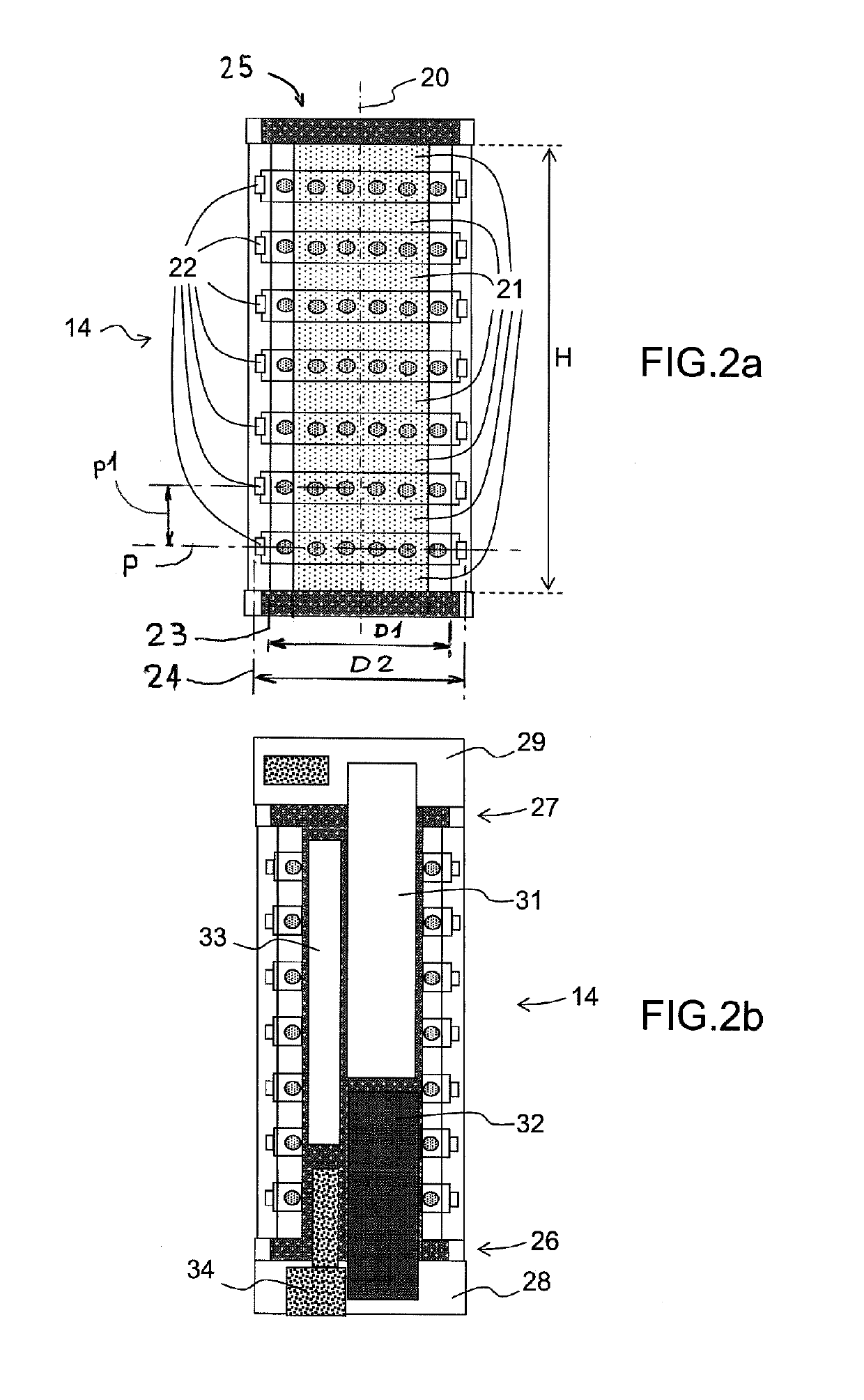
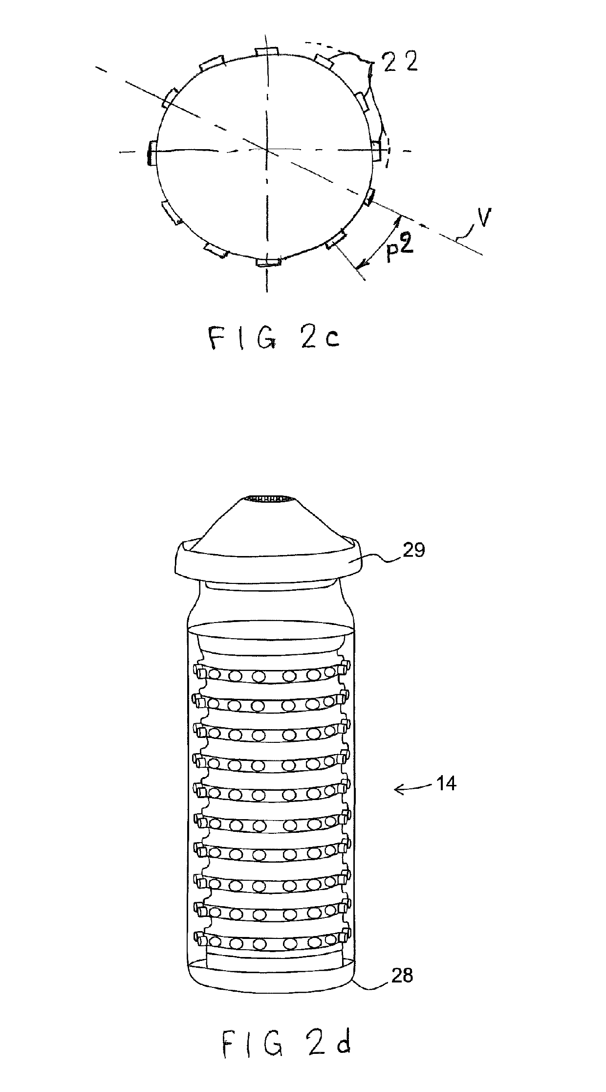
[0028]FIGS. 2a, 2b, 2c and 2d show the antenna 14. FIG. 2a shows a diagrammatic view of the outside of the active portion of the antenna 14. FIGS. 2b and 2c diagrammatically show a cross section of the antenna 14 and FIG. 2d shows a perspective view of the antenna 14.
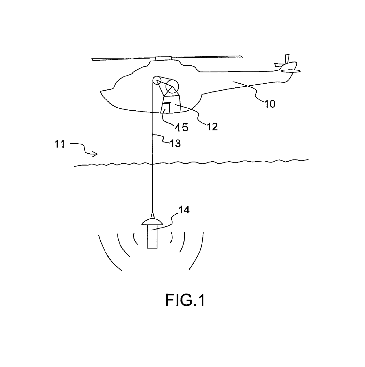
[0029]The antenna 14 is essentially cylindrical. It extends along a longitudinal axis 20. When the antenna 14 is suspended by its own weight by the cable 13, the latter also extends along the longitudinal axis 20.
[0030]The active portion of the antenna 14 is formed from sound transmitters and receivers. The transmitters are formed from elementary sound wave transmission rings 21 that are formed around the axis 20 and the receivers are formed from hydrophones 22 that are distributed in rings formed around the axis 20. An exemplary implementation of the elementary transmission rings 21 is, for example, described in the patent EP 0 799 097 B1. The hydrophones 22 are uniformly distributed around the axis 20. The hydrophones...
second embodiment
[0043]Alternatively, in this second embodiment, inner walls of the elementary transmission rings 21 are in contact with a fluid in the liquid state. This liquid may be enclosed inside the tube 25. The presence of liquid allows the acoustic performance of the antenna to be improved. In order to benefit from the advantages of the presence of a liquid without increasing the mass of the antenna, it is possible to allow the water into which the antenna 14 is dipped to come into contact with the inner walls of the elementary transmission rings 21. To this end, the antenna 40 comprises openings 41 that are arranged between the elementary transmission rings 21. These openings allow the water into which the antenna 40 is dipped to flow along inner walls 42 of the elementary transmission rings 21. Thus, when the antenna 14 is not submerged, the water bathing the interior of the antenna disappears and does not increase the mass of the antenna. When the inside of the elementary transmission rin...
third embodiment
[0048]FIG. 4 shows an antenna 50 according to the invention. The transmission rings 21 and the two structures 28 and 29 are shown again.
[0049]In this embodiment, the hydrophones 22 are not arranged in rings, but on bars 51 that are fixed to the transmission rings 21. The bars 51 may be parallel to the longitudinal axis 20. In this embodiment, it is possible to keep the supports 44 separate from the bars 51. Alternatively, the bars 51 may be used to connect the two structures 28 and 29 and replace the supports 44. The bars 51 may be positioned inside or outside the transmission rings 21.
[0050]In the various embodiments and in particular those implementing the FFR technique, it is possible to streamline the antenna in order to improve its hydrodynamic behavior.
[0051]The abandonment of the deployable antenna principle leads to a reduction in the diameter of the antenna 14, and hence an enlargement of the main lobe in the directivity diagram of the beam formed by adding up the signals f...
PUM
 Abstract
Description
Claims
Application Information
 - Generate Ideas
- Intellectual Property
- Life Sciences
- Materials
- Tech Scout
- Unparalleled Data Quality
- Higher Quality Content
- 60% Fewer Hallucinations
Browse by: Latest US Patents, China's latest patents, Technical Efficacy Thesaurus, Application Domain, Technology Topic, Popular Technical Reports.
© 2025 PatSnap. All rights reserved.Legal|Privacy policy|Modern Slavery Act Transparency Statement|Sitemap|About US| Contact US: help@patsnap.com