Surgical instrument guidance system

a surgical instrument and guidance system technology, applied in the field of medical technology, can solve the problems of difficult for physicians to determine whether the probe is punctured, the probe position is difficult to precisely set up, and the surgical site and the position are difficult to determine quickly and accurately. to achieve the effect of increasing the accuracy of the surgical instrumen

Active Publication Date: 2019-08-20
TAIWAN MAIN ORTHOPAEDIC BIOTECH CO LTD
View PDF8 Cites 8 Cited by
  • Summary
  • Abstract
  • Description
  • Claims
  • Application Information

AI Technical Summary

Benefits of technology

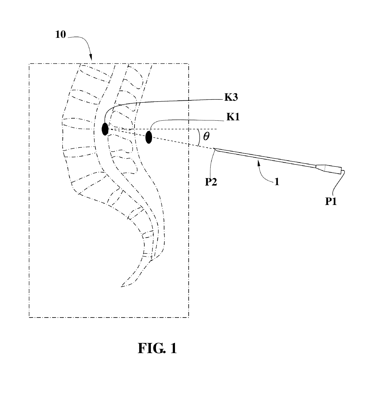
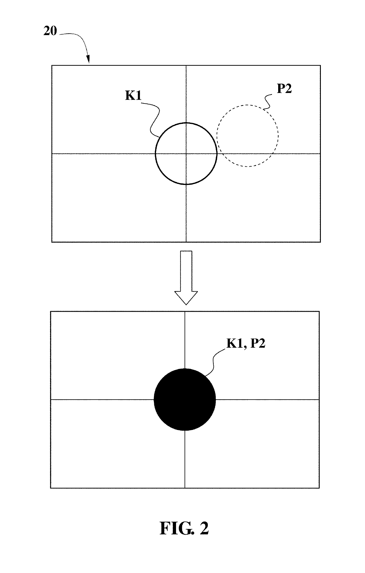
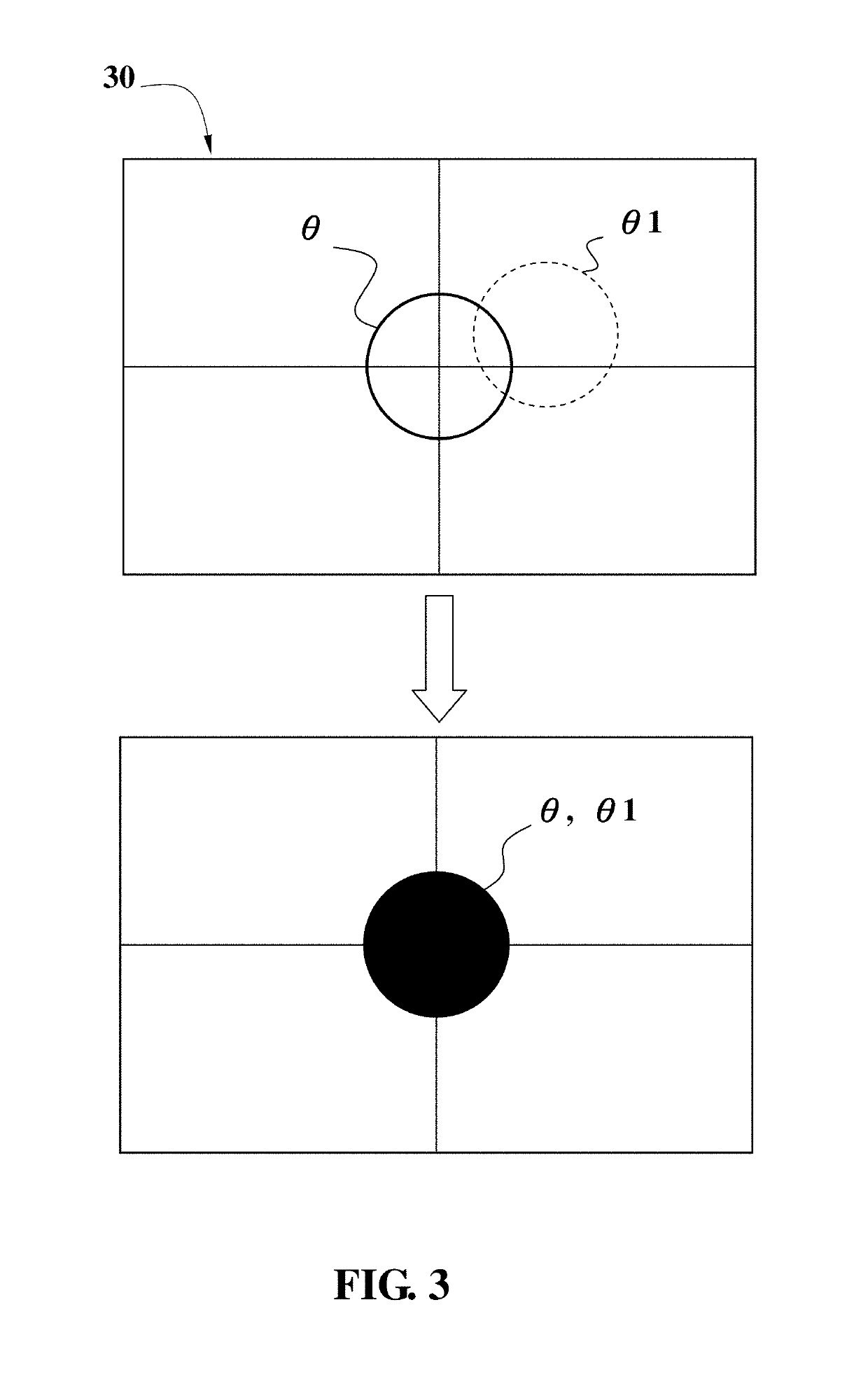
[0012]Through the smart glasses, the doctor can instantly obtain the true field of view of the surgical site of the patient, the three-dimensional medical image that coincides with the surgical site of the patient, and the real-time positional relationship between the surgical instruments and the surgical site of the patient. With the entrance guiding interface, the angle guiding interface, and the depth guiding interface, the doctor can monitor specifically and instantly whether the position relationship between the surgical instrument and the patient's surgical site conforms to the preoperative planning, and specifically increases the accuracy of the surgical instrument on the surgical site of the patient.

Problems solved by technology

Physicians, such as surgeons, need to bow down to see the surgical site while operating the site but also frequently look up or turn around to watch the display screen, making it difficult to quickly and accurately determine the surgical site and the position under the surgical knife.
Since the lesion is not exposed and the lesion is not located at the site where the endoscopic surgery can be performed, it is difficult for the physician to determine whether the probe is punctured as the probe passes through human skin and muscles into the human body to do tissue sampling of the lesion.
If the same lesion needs to be sampled at different positions or depths, the probe position will be harder to precisely set up.
However, even for orthopedists having very rich orthopedic surgical experience, large deviations of positioning accuracy could still occur.

Method used


Image

  • Surgical instrument guidance system
  • Surgical instrument guidance system
  • Surgical instrument guidance system

Examples


Embodiment Construction

[0019]In order to make the objectives, technical solutions and advantages of the present invention more comprehensible, the present invention will be further described in detail below with reference to the accompanying drawings and embodiments. It should be understood that the specific embodiments described herein are merely used to explain the present invention, and are not intended to limit the present invention.

[0020]Please refer to FIG. 5, it is a schematic view of the camera system and the smart glasses according to the present invention. The surgical instrument guidance system of the present invention comprises: a preoperative planning system, a camera system 80, a pair of smart glasses 90, an image coincidence system and a real-time surgical instrument tracking system.

[0021]The preoperative planning system is used for the construction of preoperative plan information for the doctor / physician. The preoperative plan information includes the two-dimensional medical images and th...


PUM


Abstract

Using the surgical instrument guidance system of the present invention, a doctor can instantly obtain a real field of view of a surgical site of a patient, a three-dimensional medical image that coincides with a surgical site of the patient, and a real-time positional relationship between the surgical instrument and the surgical site of the patient. The surgical instrument guidance system provides an entrance guiding interface, an angle guiding interface and a depth guiding interface to help the surgeon monitor whether the position relationship between the surgical instrument and the patient's surgical site conforms to the preoperative planning and specifically increases the accuracy of position, angle and depth of the surgical instrument on the surgical site of the patient.

Description

BACKGROUND OF THE INVENTION1. Field of the Invention[0001]The present invention relates to the field of medical technology. More particularly, the present invention relates to a surgical instrument guidance system used in surgery to solve the problem of the positional relationship between the surgical instrument and the surgical site of the patient.2. Description of the Related Art[0002]During the medical procedure, the physician must confirm the position of the surgical site and the location of the surgical knife with the help of images such as X-rays, computed tomography (CT) or magnetic resonance imaging (MRI), which are presented on the overhead display of the operating room. Physicians, such as surgeons, need to bow down to see the surgical site while operating the site but also frequently look up or turn around to watch the display screen, making it difficult to quickly and accurately determine the surgical site and the position under the surgical knife.[0003]Since the lesion ...

Claims


Application Information

Patent Timeline
Patent Type & Authority Patents(United States)
IPC IPC(8): A61B34/20A61B90/00A61B34/10A61B34/00A61B90/50G06T19/00
CPCA61B34/20A61B90/361G06T19/006A61B2034/107A61B2090/502A61B2034/252A61B2090/372A61B2090/373A61B2034/2057A61B34/10A61B90/36A61B2034/2055A61B2090/365A61B2090/371
Inventor WANG, MIN-LIANG
Owner TAIWAN MAIN ORTHOPAEDIC BIOTECH CO LTD
Why Eureka
Try Eureka