Method and apparatus for beam pattern stabilization

a beam pattern and beam pattern technology, applied in the direction of polarisation/directional diversity, instruments, baseband system details, etc., can solve the problems of high level of signalling overhead and perturbation of array orientation, and achieve the effect of improving accuracy and predicting beam pattern orientation

Active Publication Date: 2019-08-20
CAMBIUM NETWORKS
View PDF11 Cites 0 Cited by
  • Summary
  • Abstract
  • Description
  • Claims
  • Application Information

AI Technical Summary

Benefits of technology

[0012]This allows stabilisation of the MU-MIMO beam pattern without incurring the signalling overhead that may be associated with sounding the propagation channel sufficiently often to track the effects of a change in orientation of the array due to the effects of wind on a fixed installation of the access point on a tower.
[0060]In an embodiment of the disclosure, the access point may have one or more of the following features: each respective transmit chain is connected to the antenna array using printed conductors; the circuit design and physical layout of the radio frequency transmission paths for each transmit chain to the respective antenna element is the same for each antenna element; the physical layout of the access point provides a fixed spacing between the radio frequency transmission paths for each antenna element; and / or the radio frequency isolation between each antenna element is at least 30 dB at an operating frequency of the antenna element. These features may each contribute to the predictability of the beam pattern and the predictability of the relationship between azimuth angle of the beam pattern and respective phase shift values for each element. This may allow the generation of phase shift values on the basis of the output of a gyroscopic sensor to stabilise a beam pattern with improved accuracy for use at an access point of a point to multi-point wireless communication network using MU-MIMO beams.

Problems solved by technology

The antenna array may be subject to wind loading, which may be exacerbated by the height of the tower, resulting in a buffeting effect which may cause a perturbation of the orientation of the array, typically an oscillation through a small angle.
However, this may result in a high level of signalling overhead due to the frequent channel sounding.

Method used


Image

  • Method and apparatus for beam pattern stabilization
  • Method and apparatus for beam pattern stabilization
  • Method and apparatus for beam pattern stabilization

Examples


Embodiment Construction

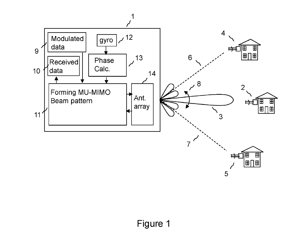
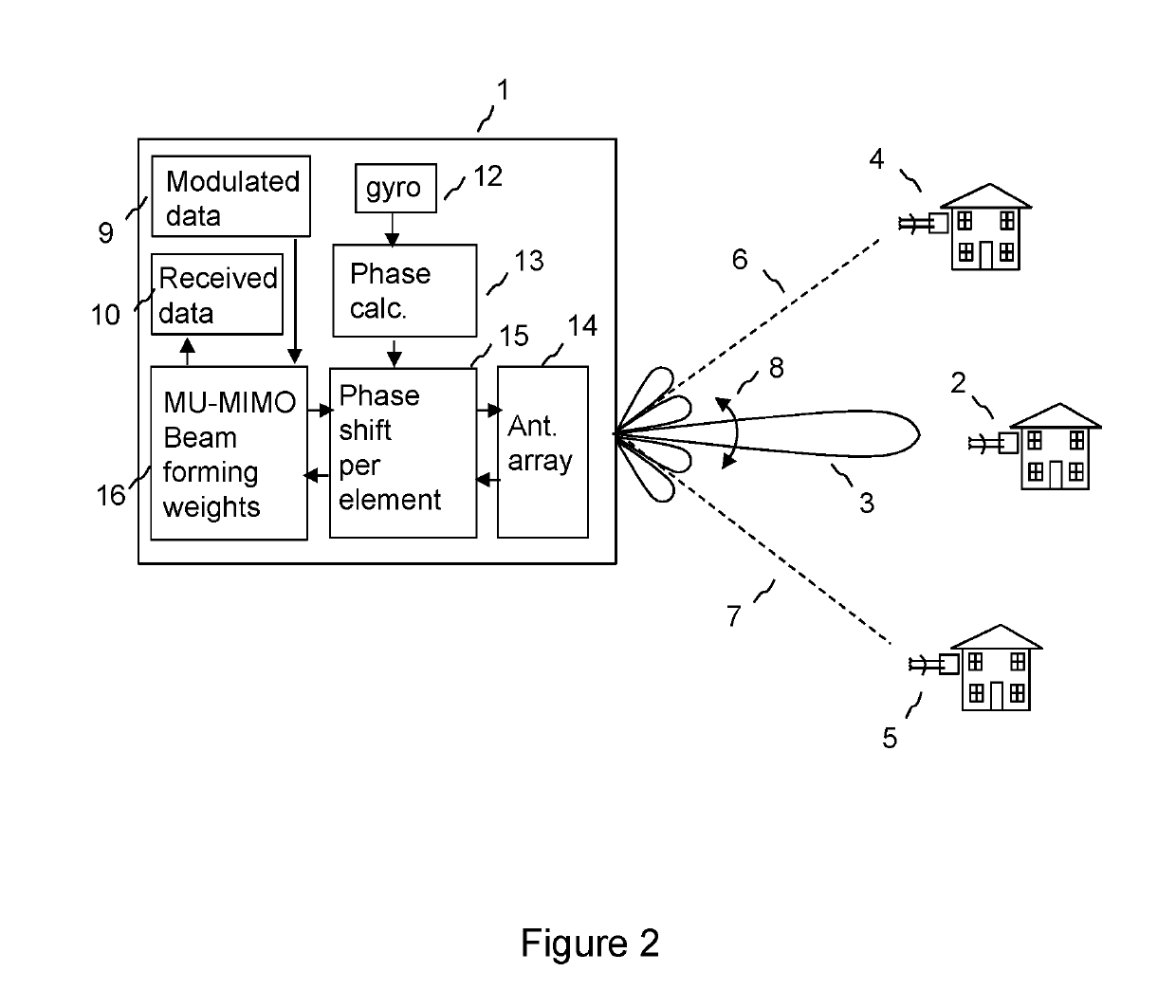
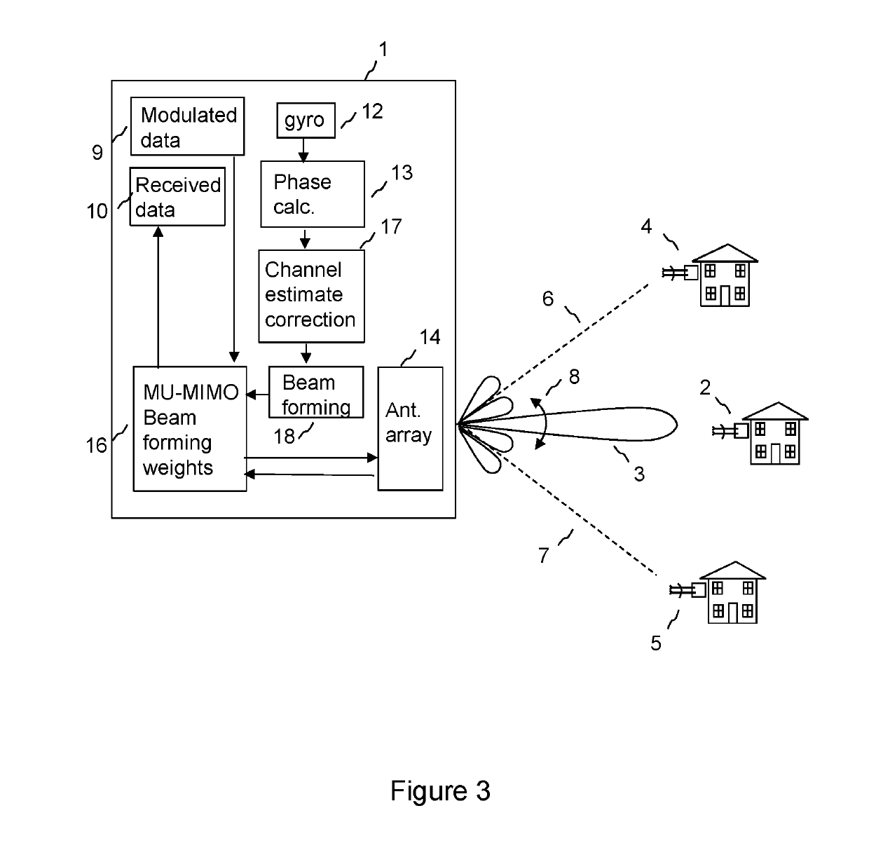
[0073]By way of example, embodiments of the disclosure will now be described in the context of a fixed wireless access system operating a time division duplex system based on IEEE 802.11 standards at carrier frequencies typically between 5 and 6 GHz. However, it will be understood that this is by way of example only and that other embodiments may involve other wireless systems and frequencies, and embodiments are not restricted to a specific frequency band of operation or a specific standard, and may involve operation in licensed or unlicensed bands.

[0074]FIGS. 1, 2 and 3 are schematic diagrams showing an access point 1 according to embodiments of the disclosure for use in a point to multipoint wireless communication network comprising the access point and a plurality of subscriber modules 2, 4, 5. The access point 1 has an array 14 of antenna elements, each element being arranged to transmit a signal that is appropriately weighted in amplitude and phase to form a Multi User Multipl...


PUM


Abstract

Methods and apparatuses for beam pattern stabilization are provided. A method may include processing an output of a gyroscopic sensor to generate a plurality of first phase corrections for a first time interval and a plurality of second phase corrections for a second time interval. The method may further include measuring respective signal propagation characteristics between each antenna element of the array and each of a first and second subscriber module for the first time interval. The method may further include forming, based on the measured respective signal propagation characteristics, the plurality of first phase corrections, and the plurality of second phase corrections, a MU-MIMO beam pattern for the second time interval having a main lobe towards the first subscriber module and a null towards the second subscriber module, whereby to correct for a change in orientation of the array between the first time interval and the second time interval.

Description

RELATED APPLICATIONS[0001]This application claims the benefit of UK Patent Application No. GB 1608425.3, filed May 13, 2016, and entitled “METHOD AND APPARATUS FOR BEAM PATTERN STABILISATION,” the entire contents of which is incorporated herein by reference.BACKGROUND1. Technical Field[0002]The present disclosure relates generally to an access point in a point to multipoint wireless network and to methods of operating the access point, and more specifically, but not exclusively, to a method of stabilisation of a beam pattern emitted from or received by an array of antenna elements at an access point of a wireless communication network.2. Background[0003]Modern wireless communication networks are typically placed under great demands to provide high data capacity within the constraints of the allocated signal frequency spectrum. In cellular wireless communication networks, capacity may be increased by re-using frequencies between cells, typically according to a predetermined frequency...

Claims


Application Information

Patent Timeline
Patent Type & Authority Patents(United States)
IPC IPC(8): H04B7/0456H04L5/14H04B7/06G01C19/00G01C21/18G01P5/18H04L25/02H04B7/0452G01P15/18H04B7/10
CPCH04B7/0456G01C19/00G01C21/18G01P15/18H04B7/0452H04B7/0617H04L5/14H04L25/0206H04L25/0228H04B7/10H04L25/0204H01Q1/185
Inventor STRONG, PETER
Owner CAMBIUM NETWORKS
Why Eureka
Try Eureka