Method and X-ray device for temporal up-to-date representation of a moving section of a body, computer program product and data carrier

a technology of moving parts and x-ray devices, which is applied in the field of computer implementation methods and x-ray devices for temporal up-to-date representation of moving parts of bodies, can solve the problems of damage and malfunction of the aorta valve, too much contrast agent administration, and the aorta root barely being visible in fluoroscopy, so as to achieve the effect of high precision of movement compensation

Active Publication Date: 2019-08-27
SIEMENS HEALTHCARE GMBH
View PDF24 Cites 17 Cited by
  • Summary
  • Abstract
  • Description
  • Claims
  • Application Information

AI Technical Summary

Benefits of technology

[0012]The idea underlying the disclosed solution of the afore-cited object is to use the 3D ultrasound images as an intermediary in each instance, in order to create third 2D x-ray images extended with additional information for instance from the second 2D x-ray images using the first x-ray image data record and then to indicate these. The recording of the 3D ultrasound images and the 2D x-ray images takes place at the same time and in real time, i.e. with a high temporal resolution. It is possible to update the position of the moving section in the 2D x-ray images in real time. This takes place by determining and updating the position of the afore-cited model of the moving section on the respective 3D ultrasound image, registering the 3D ultrasound image with the 2D x-ray image and then providing a superimposed representation of the updated model with the 2D x-ray image recorded in real time. In other words, the 3D ultrasound images are used to update and / or represent in real time the position of the moving section (from which it is assumed that it is clearly visible in the 3D ultrasound images but nevertheless scarcely visible or not visible at all in the 2D x-ray image) in the respective 2D x-ray image, without being assigned to a 3D x-ray image, such as is the case with the merged representation of the first x-ray image data record. In this way, moving sections in the 2D x-ray images can be shown in real time without being directly detectable by the 2D x-ray image recording. It is herewith possible in accordance with the application to be able to display all details of two different image acquisition and / or image creation systems in a single image in real time and / or without a temporal delay.
[0013]The ultrasound image generation is in many respects complementary to x-ray fluoroscopy. While ultrasound image generation provides a soft tissue contrast and a spatial representation, which enables easy visualization of complex heart anatomies and valve functions, catheters etc. are usually more clearly visible in fluoroscopy.
[0014]The disclosed method is also advantageous in that no new equipment for image acquisition or image preparation has to be installed in an operating room already equipped with various equipments, since the ultrasound image generation unit is generally already present and used in heart valve operations.
[0029]The present application is advantageous in that an electromagnetic tracking method can update the orientation and position of an ultrasound probe, such as a TEE probe, at any time in real time and fully automatically.
[0030]It also remains to be emphasized that when using the disclosed method, higher precision of the movement compensation can be achieved than for instance when tracing the head of a catheter. Applying the disclosed method ensures that position deviations of the represented areas from reality amount to 2 mm at most.

Problems solved by technology

Failure of the aortic valve, which is among the most frequent of valve faults, frequently results in damage and malfunction of the aortic valve.
The problem nevertheless arises here of the aorta root barely being visible in the fluoroscopy images, if no contrast agent is injected.
Administration of (too much) contrast agent may however be problematic in many instances, because this may result for instance in renal insufficiency and injury to the patient.
A movement synchronization of this type is however currently only possible at the cost of a very high and thus possibly damaging contrast agent administration for the constant recording of a three-dimensional x-ray image.

Method used


Image

  • Method and X-ray device for temporal up-to-date representation of a moving section of a body, computer program product and data carrier

Examples


Embodiment Construction

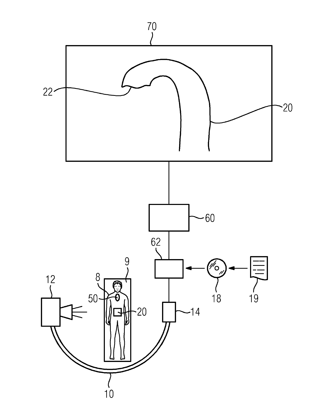
[0036]The FIGURE shows a schematic representation of an x-ray device 10 embodied as a C-arm device, which includes an x-ray emitter 12 which can be pivoted in respect of the angular position and an x-ray detector 14 assigned and fixedly connected to the x-ray emitter 12. A patient 8 for diagnosis or therapy, such as for implantation of an aortic valve, can be arranged on a patient couch 9 between the x-ray emitter 12 and the x-ray detector 14.

[0037]The x-ray device 10 creates a required 3D x-ray image and “live” 2D x-ray images during an operation. Furthermore, a TEE probe 50 is shown in the esophagus of the patient 8, with which 3D ultrasound images can be generated during the operation, of the heart and / or aorta and / or its root.

[0038]A control apparatus 62, for instance in the form of a computer, is connected to the x-ray detector 14, said computer being connected to an x-ray image generation unit 60 for generating image data records from the data recorded by the x-ray detector 14...


PUM


Abstract

A computer-implemented method for temporal up-to-date representation of a moving section of a body is provided. A first x-ray image data record is provided containing the moving section in a specific movement phase and a first 2D x-ray image and a 3D x-ray image superimposed and registered with one another. 2D x-ray images are repeatedly recorded each containing the moving section. 3D ultrasound images are repeatedly recorded each containing the moving section. Extended 2D x-ray images are created from the 2D x-ray images using the first x-ray images data record. The 3D ultrasound images are used as intermediaries for movement correction. The extended 2D images are displayed.

Description

CROSS REFERENCE TO RELATED APPLICATIONS[0001]This application claims priority of German application No. 10 2011 079 561.8 filed Jul. 21, 2011, which is incorporated by reference herein in its entirety.FIELD OF INVENTION[0002]The present application relates to a computer-implemented method and an x-ray device for temporal up-to-date representation of a moving section of a body. The application further relates to a computer program product, which implements the method, as well as a data carrier having a stored computer program product.BACKGROUND OF INVENTION[0003]Consistent attempts are made to improve medical imaging during interventions, wherein as few s as possible are simultaneously to be radiated onto the body of a patient. It is in many instances also very desirable to keep the stress on the body, such as on the kidneys, caused by the contrast agent which is required for x-ray recordings, to a minimum. One example to which this applies is the insertion of a new aortic valve. Thi...

Claims


Application Information

Patent Timeline
Patent Type & Authority Patents(United States)
IPC IPC(8): A61B8/00A61B6/00A61B8/08A61B8/12A61B34/20A61B90/00
CPCA61B6/4441A61B6/487A61B6/488A61B6/503A61B6/504A61B6/5235A61B6/5247A61B6/5264A61B8/0883A61B8/0891A61B8/12A61B8/4254A61B8/483A61B8/5261A61B8/5276A61B2034/2051A61B2090/364A61B2090/376A61B2090/378
Inventor HAN, JING FENGJOHN, MATTHIAS
Owner SIEMENS HEALTHCARE GMBH
Why Eureka
Try Eureka