Deposition of non-uniform non-overlapping curvilinear segments of anisotropic filament to form non-uniform layers

a curvilinear segment and anisotropic filament technology, applied in the field of additive manufacturing of three-dimensional objects, can solve the problems of not being able to deposit a run inside the surface of the surface, affecting the quality of the finished product, etc., and achieves the effect of cost and disadvantages of traditional additive manufacturing

Active Publication Date: 2019-08-27
STRATSYS INC
View PDF1 Cites 71 Cited by
  • Summary
  • Abstract
  • Description
  • Claims
  • Application Information

AI Technical Summary

Benefits of technology

[0017]For example, some embodiments of the present invention are able to deposit a series of layers of material such that the thickness of each layer at each location in the layer can be controlled. This enables each layer to have a uniform or non-uniform thickness, a planar or non-planar contour, and adjacent layers to morph from one contour to another.
[0018]In accordance with the illustrative embodiment, this is achieved by fabricating each layer from one or more non-overlapping curvilinear segments of anisotropic filament and by controlling the deposition height of each curvilinear segment at each location. In other words, by having an additive manufacturing process that can controllably vary the height of each curvilinear segment, the contour of each layer can be controlled to affect the overall characteristics of the object. This is, for example, advantageous for manufacturing objects with non-planar surfaces (e.g., airplane wings, ducts, propellers, axels, etc.) and objects that require non-planar internal structures to achieve desired characteristics.

Problems solved by technology

To accomplish this, however, there are constraints on the sequence in which the runs can be deposited.
Second, when a three-dimensional surface is sealed, it is no longer possible to deposit a run inside of that surface.
There are, however, costs and disadvantages associated with traditional additive manufacturing.

Method used


Image

  • Deposition of non-uniform non-overlapping curvilinear segments of anisotropic filament to form non-uniform layers
  • Deposition of non-uniform non-overlapping curvilinear segments of anisotropic filament to form non-uniform layers
  • Deposition of non-uniform non-overlapping curvilinear segments of anisotropic filament to form non-uniform layers

Examples


Embodiment Construction

[0039]For the purposes of this specification, the following terms and their inflected forms are defined as follows:[0040]The term “horizontal” is defined as parallel to the X-Y plane.[0041]The term “vertical is defined as normal to the X-Y plane.[0042]The term “height” is defined as the maximum vertical range.[0043]The term “top” is defined as the highest vertical extent.[0044]The term “bottom” is defined as the lowest vertical extent.[0045]The term “watertight” is defined as closed mathematical surface.

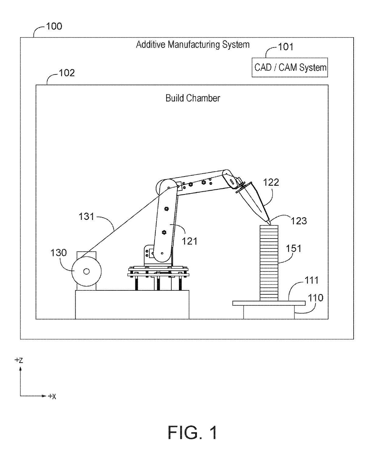
[0046]FIG. 1 depicts an illustration of the salient components of additive manufacturing system 100 in accordance with the illustrative embodiment of the present invention. Additive manufacturing system 100 comprises: CAD / CAM system 101, build chamber 102, turn-table 110, deposition platform 111, robotic arm 121 (which itself comprises deposition head 122 and deposition needle 123), thermoplastic filament spool 130, and thermoplastic filament 131. The purpose of manufacturing system ...


PUM

PropertyMeasurementUnit
thicknessaaaaaaaaaa
thermoplasticaaaaaaaaaa
melting pointaaaaaaaaaa

Abstract

A process of additive manufacturing in which a stack of non-planar layers of material are deposited for manufacturing an object. The non-planar layers can conform to the surface of the object or not. The non-planar layers can create structurally-advantageous interior structures in the object. The contours of the non-planar layers can be different or can be the same.

Description

STATEMENT OF RELATED APPLICATIONS[0001]The following patent applications are incorporated by reference for the description of how to make and use additive manufacturing system 100:[0002]U.S. patent application Ser. No. 15 / 438,559, filing date Feb. 21, 2017;[0003]U.S. patent application Ser. No. 15 / 375,832, filing date Dec. 12, 2016;[0004]U.S. patent application Ser. No. 15 / 232,767, filing date Aug. 9, 2016;[0005]U.S. patent application Ser. No. 14 / 574,237, filing date Dec. 17, 2014; and[0006]U.S. patent application Ser. No. 14 / 623,471, filing date Feb. 16, 2015.FIELD OF THE INVENTION[0007]The present invention relates to additive manufacturing of three-dimensional object in general, and, more particularly, to techniques for fabricating objects with non-orthogonal surfaces and internal structures.BACKGROUND[0008]Additive manufacturing is a technique for building a three-dimensional object from a mathematical model of the object. In the additive manufacturing technique called fused-de...

Claims


Application Information

Patent Timeline
Patent Type & Authority Patents(United States)
IPC IPC(8): B29C64/386B33Y50/02B29C64/393B33Y80/00B29C70/38B33Y10/00B33Y50/00B29C64/118
Inventor MONDESIR, WIENER
Owner STRATSYS INC
Why Eureka
Try Eureka