Output director vane for an aircraft turbine engine, with an improved lubricant cooling function using a heat conduction matrix housed in an inner duct of the vane

a technology of air turbine engine and heat conduction matrix, which is applied in the direction of machines/engines, laminated elements, light and heating apparatus, etc., can solve the problems that the solutions proposed in the prior art remain perfectible, and achieve the effect of easily varying the density of the main conduction heat fin

Active Publication Date: 2019-08-27
SN DETUDE & DE CONSTR DE MOTEURS DAVIATION S N E C M A
View PDF14 Cites 5 Cited by
  • Summary
  • Abstract
  • Description
  • Claims
  • Application Information

AI Technical Summary

Benefits of technology

[0011]Thus, the orientation and arrangement of the fins provide a satisfactory mechanical strength and high heat performance, while limiting the load losses suffered by the lubricant traversing through the first inner duct equipped in the fins.
[0013]The director vane includes, at the level of the foot or the head of the vane, an opening for the introduction of the first heat conduction matrix in the first interior duct. The location of the opening introduction significantly reduces the risk of leakage and of accidental introduction of lubricant in the fan air flow. On the other hand, this design allows creating vane parts in a single pass that bound the first inner duct, to obtain a better mechanical strength.
[0018]In addition, said first duct may define a lubricant thawing channel extending along the first main direction, said channel being devoid of fins all along it and along the first heat conduction matrix. Alternatively, it may be a channel in which the main wings of the first matrix are located, but in a lower density than that adopted in the adjacent areas. In both cases, this allows to manage the specific flight phases in which the lubricant drops to very low temperatures, giving it a high viscosity. Indeed, thanks to this so-called “thawing” channel planned within the first inner duct, the lubricant can flow easier through this duct through the dedicated channel, and allows at the same time to warm the frozen lubricant between the fins of the zones adjacent to said channel. In this respect, it is stated that thawing channel is preferentially planned at one of the ends of the first inner duct, depending on the transverse direction of the latter.
[0022]According to another possibility, the fluids of the first and second inner ducts are connected to one another near the head of the vane, and the average density of fins within the first inner duct is preferably less than the density of fins within the second inner duct. Indeed, since the lubricant is colder in the return direction adopted within the second inner duct, it makes it possible to increase the heat power exchanged by increasing the average fin density in this second duct.
[0025]Finally, the invention is a method for manufacturing such a guide vane, the said aerodynamic vane part being made from a single piece so as to reveal the first inner duct, and the first heat conduction matrix is inserted in the said first inner duct. The matrix can be produced in a conventional manner, or else using the additive manufacturing technique. It is noted that the additive manufacturing proves to be perfectly suited to the production of the heat conduction matrix, in particular because this technique makes it possible to easily vary the density of the main conduction heat fins.

Problems solved by technology

However, the solutions proposed in the prior art remain perfectible.

Method used


Image

  • Output director vane for an aircraft turbine engine, with an improved lubricant cooling function using a heat conduction matrix housed in an inner duct of the vane
  • Output director vane for an aircraft turbine engine, with an improved lubricant cooling function using a heat conduction matrix housed in an inner duct of the vane
  • Output director vane for an aircraft turbine engine, with an improved lubricant cooling function using a heat conduction matrix housed in an inner duct of the vane

Examples


Embodiment Construction

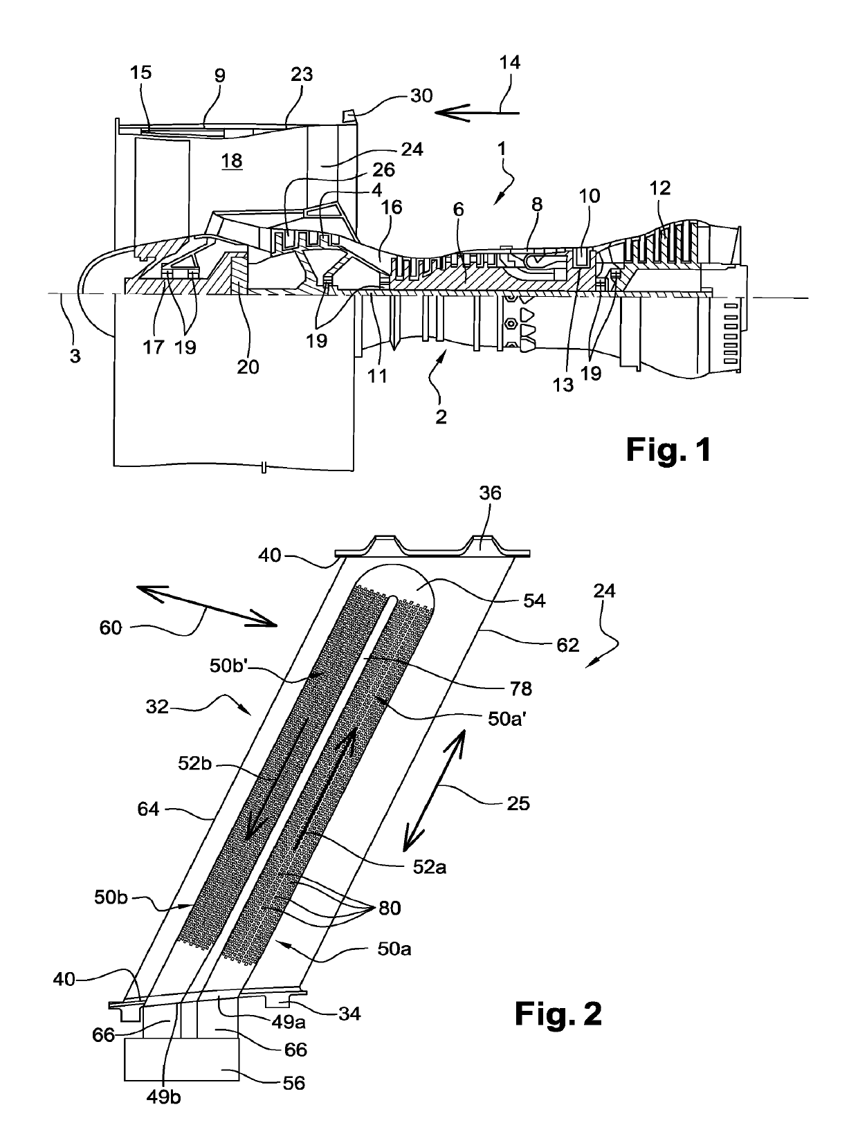
[0042]With reference to FIG. 1, it represents a dual-flow and a dual-body turbojet 1, with a high dilution rate. The turbojet 1 is classically comprised of a gas generator 2 on either sides of which are arranged a low pressure compressor 4 and one low pressure turbine 12, this gas generator 2 comprising a high pressure compressor 6, a combustion chamber 8 and a high pressure turbine 10. Subsequently, the terms “front” and “back” are considered in an opposite direction 14 to the main flow direction of the gases within the turbojet, this direction 14 being parallel to its longitudinal axis 3. However, the terms “upstream” and “downstream” are considered according to the main flow direction of the gas within the turbojet.

[0043]The low pressure compressor 4 and the low pressure turbine 12 form a low pressure body, and are connected to each other by a low-pressure shaft 11 centred on the axis 3. Similarly, the high pressure compressor 6 and the high-pressure turbine 10 form a high pressu...


PUM


Abstract

A guide vane for a dual flow aircraft turbine engine, the aerodynamic part of the vane including an inner duct for lubricant cooling extending in a main direction and being partly bounded by a pressure side wall and a suction side wall of the vane. A heat conduction matrix is lodged in the duct, and presents main heat transfer wings extending parallel to the direction, and laid out in staggered rows.

Description

TECHNICAL FIELD[0001]This invention relates to the aircraft dual flow turbine engines field, and in particular the design of guide vanes arranged in the entirety or part of an air flow from a turbine engine fan.[0002]This pertains preferably to outlet guide vanes, also known as OGV, designed to straighten the airflow at the fan outlet. Alternatively or simultaneously, if necessary, guide vanes could be placed at the fan inlet. The guide vanes are classically arranged in the turbine engine secondary vein.[0003]The invention preferably pertains to an aircraft turbojet equipped with such outlet guide vanes.PRIOR STATE OF THE ART[0004]On some dual-flow turbojets, there have been instances where the outlet guide vanes are implemented downstream of the fan to straighten the flow coming out of it, and also eventually to provide a structural function. This last function is indeed intended to allow the duct of efforts from the centre of the turbine engine to an outer ring located in the exte...

Claims


Application Information

Patent Timeline
Patent Type & Authority Patents(United States)
IPC IPC(8): F01D9/06F02C7/14F02C3/04F28F3/02F28D21/00
CPCF01D9/065F02C7/14F05D2220/36F05D2250/182F05D2260/22141F28D2021/0021F28D2021/0089F28F3/027Y02T50/60F01D5/18F01D25/18F28D1/02F28F1/06F28F1/40F02C3/04F05D2220/323F05D2230/50F05D2260/232
Inventor ZACCARDI, CEDRICBOUTALEB, MOHAMED-LAMINECHALAUD, SEBASTIEN CHRISTOPHELEMARECHAL, ERIC PIERRE GEORGESPAPIN, THIERRY GEORGES PAUL
Owner SN DETUDE & DE CONSTR DE MOTEURS DAVIATION S N E C M A
Why Eureka
Try Eureka