Constant velocity joint

a constant velocity, joint technology, applied in the direction of couplings, mechanical equipment, rotary machine parts, etc., can solve the problems of reducing the strength of the base portion of the tripod shaft and deteriorating the torque transmission efficiency, so as to reduce the deterioration of strength, efficient transmission of torque, and constant velocity

Active Publication Date: 2019-08-27
JTEKT CORP
View PDF3 Cites 0 Cited by
  • Summary
  • Abstract
  • Description
  • Claims
  • Application Information

AI Technical Summary

Benefits of technology

[0007]An object of the present invention is to provide a constant velocity joint that can efficiently transmit torque while reducing the deterioration of strength.
[0015]In the constant velocity joint of the aspect of the present invention, the recess portion includes the first concave portion, which is formed in a position where the first concave portion is recessed toward the base side of the leg shaft with respect to the contact portion. In this case, even when the curvature radius of the recess portion is increased, since the connection position between the roll portion and the recess portion can be positioned closer to the base side of the leg shaft, a sufficient axial length of the roll portion can be ensured. Thus, the torque can be efficiently transmitted between the outer joint member and the inner joint member, while the deterioration of the strength can be reduced.

Problems solved by technology

In the technique described in JP 2012-197832 A, however, if a curvature radius of the recess groove is decreased, the stress concentrates on a portion in which the recess groove is formed, reducing the strength of the base portion of the tripod shaft.
This causes wear of the torque transmission surface and the shaft-like rolling element, possibly deteriorating torque transmission efficiency.

Method used


Image

  • Constant velocity joint
  • Constant velocity joint

Examples


Embodiment Construction

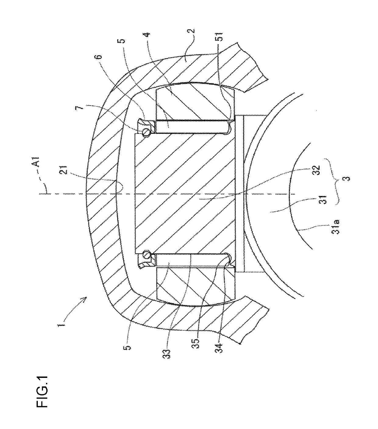
[0020]Hereinafter, an embodiment to which a constant velocity joint of the present invention is applied will be described with reference to the accompanying drawings. First, a constant velocity joint 1 of one embodiment of the present invention will be schematically described with reference to FIG. 1.

[0021]As shown in FIG. 1, the constant velocity joint 1 is a tripod constant-velocity joint of a single roller type, and is used at, for example, a coupling portion between a differential gear of a vehicle and an intermediate shaft of a drive shaft. The constant velocity joint 1 mainly includes an outer joint member 2, an inner joint member 3, three rollers 4, a plurality of needle bearings (needle roller bearings) 5, three retainers 6, and three locating snap rings 7.

[0022]The outer joint member 2 is formed like a closed-end cylinder, and is provided, on an outer side of the bottom of the outer joint member 2, with a stem (not shown) that is connected to the differential gear (not show...


PUM


Abstract

A constant velocity joint includes: an outer joint member having a raceway groove; an inner joint member having a leg shaft; a roller that is able to roll on the raceway groove; and a needle bearing that supports an inner periphery of the roller such that the inner periphery of the roller is able to rotate with respect to the leg shaft. The leg shaft includes: a roll portion that supports the needle bearing; a contact portion that is able to contact an end face of the needle bearing, the end face facing a first side in the direction of a central axis of the needle bearing; and a recess portion formed between the roll portion and the contact portion, in a position where the recess portion is recessed from a space in which the needle bearing is disposed.

Description

INCORPORATION BY REFERENCE[0001]The disclosure of Japanese Patent Application No. 2016-033116 filed on Feb. 24, 2016 including the specification, drawings and abstract, is incorporated herein by reference in its entirety.BACKGROUND OF THE INVENTION[0002]1. Field of the Invention[0003]The present invention relates to a constant velocity joint.[0004]2. Description of the Related Art[0005]A constant velocity joint is known to have an outer joint member having a plurality of raceway grooves extending in an axial direction, and an inner joint member having a plurality of leg shafts inserted in the raceway grooves. Japanese Patent Application Publication No. 2012-197832 (JP 2012-197832 A) discloses a tripod shaft (leg shaft) in which a recess groove is formed between a torque transmission surface having a circular cross section and a seat protruding outward in a radial direction with respect to the torque transmission surface. The recess groove is a portion formed to prevent interference ...

Claims


Application Information

Patent Timeline
Patent Type & Authority Patents(United States)
IPC IPC(8): F16D3/205F16C1/00F16C33/34F16C33/58F16D3/202
CPCF16D3/221F16C19/466F16C33/34F16C33/585F16C2361/41F16D3/2055Y10S464/905F16C1/00F16D2003/2026
Inventor KOBATA, KEISHI
Owner JTEKT CORP
Why Eureka
Try Eureka