
Connection structure and connection system

A technology for connecting structures and connecting bodies, which is applied in the direction of connecting components, thin-plate connections, and testing of machine/structural components. It can solve problems such as difficulty and the external heat-proof structure of the aircraft cannot bear the compression load, etc.

Active Publication Date: 2021-09-14
BEIJING AEROSPACE TECH INST
View PDF8 Cites 0 Cited by
  • Summary
  • Abstract
  • Description
  • Claims
  • Application Information

AI Technical Summary

Problems solved by technology

However, the ring clamp structure will achieve a tight compressive force on the connecting parts; while the size of large high-speed aircraft and its sections are large, and the outer heat-resistant structure of the aircraft cannot bear the additional compressive load, so , for large high-speed aircraft and its sections, such as the cabin structure, it is more difficult to connect with the ring clamp structure

Method used


Image

  • Connection structure and connection system
  • Connection structure and connection system
  • Connection structure and connection system

Examples


Embodiment 1

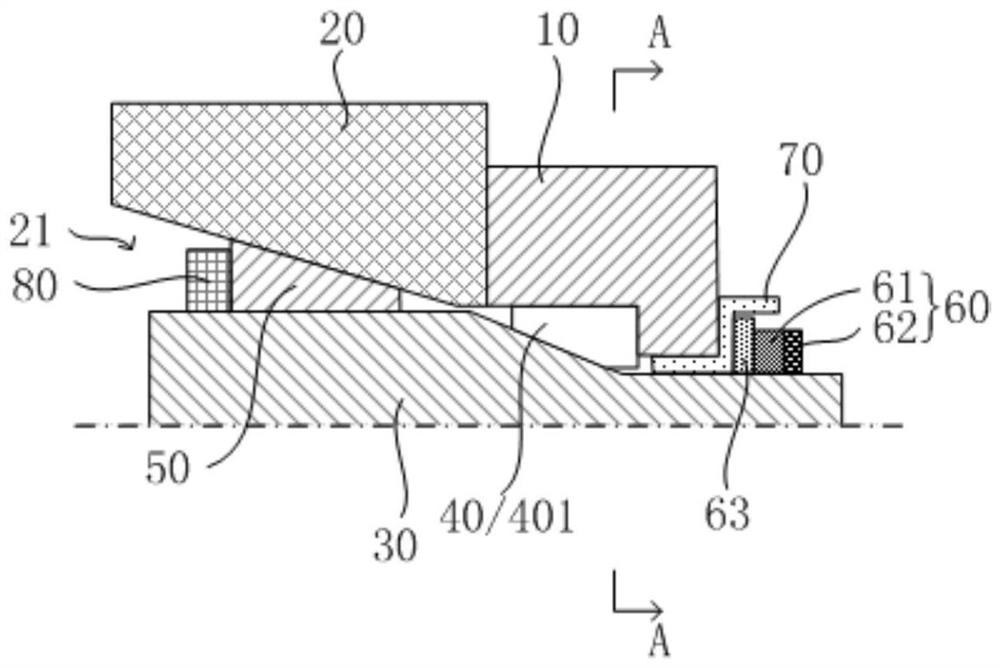
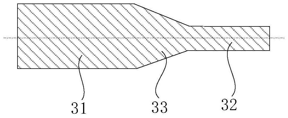
[0041] The present invention provides a connection structure, such as figure 1 , Figure 3-Figure 5 As shown, the connecting structure includes: a first connecting body 10, a second connecting body 20, a tapered stud 30, a tapered fitting structure 40, a tapered nut 50 and a set nut 60; the first connecting body 10 is provided with a connection Through hole 11 and limiting through hole 12, the inner diameter of limiting through hole 12 is greater than the inner diameter of connecting through hole 11; The holes 11 are distributed sequentially; the tapered stud 30 passes through the tapered hole 21, the limiting through hole 12 and the connecting through hole 11 in sequence, and the tapered stud 30 has a first cylindrical part 31, a tapered part 33 and a second cylindrical part connected in sequence. Two cylindrical parts 32; the conical fitting structure 40 is located in the limiting through hole 12, the conical fitting structure 40 is provided with the first tapered surface 4...

Embodiment 2

[0057] The present invention provides a connection system such as Figure 8 As shown, the connecting system includes: a plurality of the above-mentioned connecting structures 1 , the first connecting bodies 10 of each connecting structure 1 are connected as a whole, and the second connecting bodies 20 of each connecting structure 1 are connected as a whole. For example, the whole formed by the connected first connecting bodies 10 is the cabin structure 2 or a part of the cabin structure 2; the whole formed by the connected second connecting bodies 20 is a vibration test transfer structure. 3 or part thereof.

[0058] Figure 8 The connection system shown can be implemented with the following assembly methods:

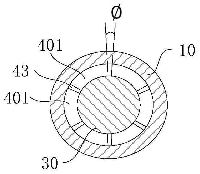
[0059] Step S10: Place the conical fitting blocks 401, and uniformly reserve a circumferential gap 43 between each conical fitting block 401 in the circumferential direction;

[0060] Step S20: Install the interface conversion sleeve 70, and use anti-loose glue to pr...


PUM


Abstract

The invention provides a connection structure and a connection system, the connection structure includes a first connection body, which is provided with a connection through hole and a limiting through hole; a second connection body, which is provided with a tapered hole, a tapered hole, a limiting through hole Bit through holes and connecting through holes are distributed sequentially; tapered studs pass through the tapered holes, limiting through holes and connecting through holes, and the tapered studs have a first cylindrical part, a tapered part and a second connected in sequence. Cylindrical part; a conical fitting structure arranged in the limiting through hole, the conical fitting structure is provided with a first conical surface matched with the tapered part, and a limiting cylindrical surface matched with the inner wall of the limiting through hole; The tapered nut screwed on the first cylindrical part, the tapered nut is provided with a second tapered surface matching the tapered hole; the set nut screwed on the second cylindrical part, the set nut and the first connecting body The end surface facing away from the second connecting body abuts. Through the present invention, the technical problem that it is difficult to effectively transmit the vibration load to the aircraft or its sections in the vibration test of the large aircraft is alleviated.

Description

technical field [0001] The invention relates to the technical field of aircraft test equipment, in particular to a connection structure and a connection system. Background technique [0002] High-speed aircraft fly at a high speed and have a large mass, so they will bear a large vibration load during flight. In order to ensure the reliability of the aircraft structure, internal equipment and cables under vibration loads during flight, it is necessary to carry out ground vibration tests for the entire aircraft and aircraft sections for assessment and verification. In the ground vibration test, it is necessary to ensure that the vibration load borne by the aircraft structure, internal equipment and cables in the ground vibration test is not too large and the assessment is too strict, or too small and the assessment is insufficient. Therefore, the aircraft and aircraft sections, and vibration The transmission performance of the connection structure of the test adapter to the v...

Claims


Application Information

Patent Timeline
Patent Type & Authority Patents(China)
IPC IPC(8): F16B5/02F16B35/04F16B37/04F16B39/12F16B43/02G01M7/02B64F5/60
CPCB64F5/60F16B5/025F16B35/041F16B37/042F16B39/12F16B43/02G01M7/027
Inventor 吴蓓蓓罗俊航霍浩亮蔡逸如李明春张珊张博昌解建恒李奥
Owner BEIJING AEROSPACE TECH INST
Learn More