End point closing wall forming device of extrusion type underground diaphragm wall and method for operating same
a diaphragm wall and end point technology, applied in the field of underground space development and continuous wall closure devices of pressin type, can solve the problems of inability to achieve effective waterproofing, weak overlapping structure, and approach that cannot meet the technical requirements of waterproofing, soil retention, and weight bearing, and achieve reliable wall quality and save resources.
- Summary
- Abstract
- Description
- Claims
- Application Information
AI Technical Summary
Benefits of technology
Problems solved by technology
Method used
Image
Examples
example 1
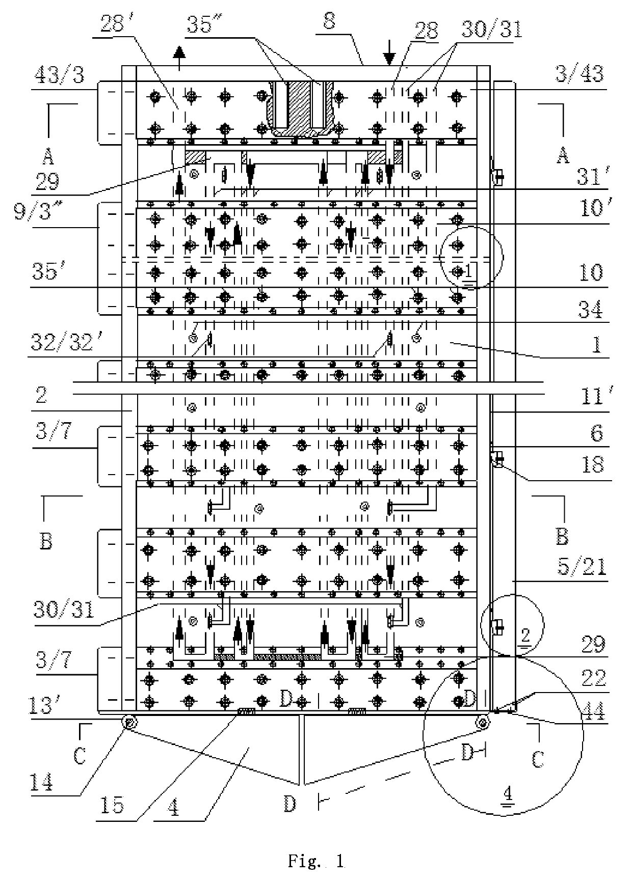
[0034]As shown in FIG. 1, which is an elevation view of a wall closure device, a device of the invention includes a main body 1, a separation device, and a vibration water-spray device. The vibration water-spray device is set within the main body 1 and is fixed with the main body 1. A device of the invention also includes a separation device, which is disposed on the outside of the main body 1 and is moveably attached to the main body 1.
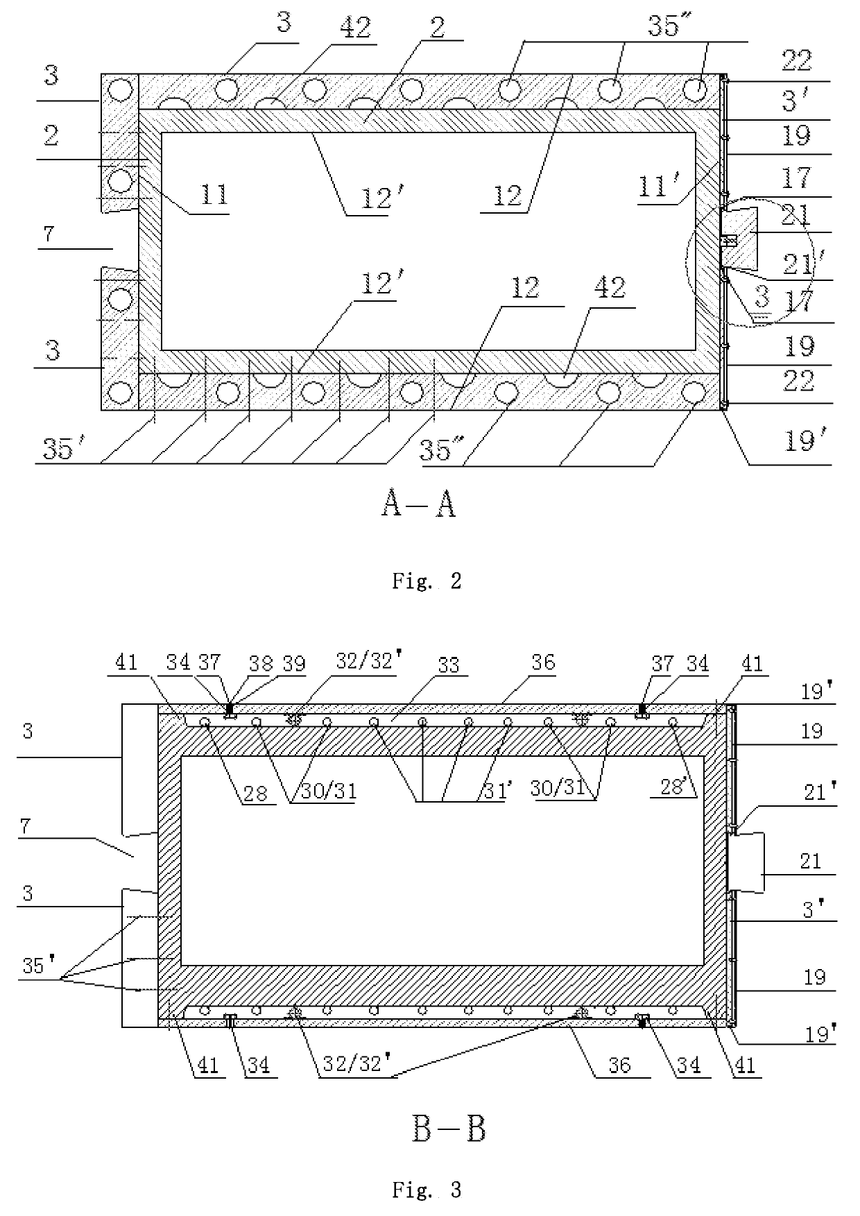
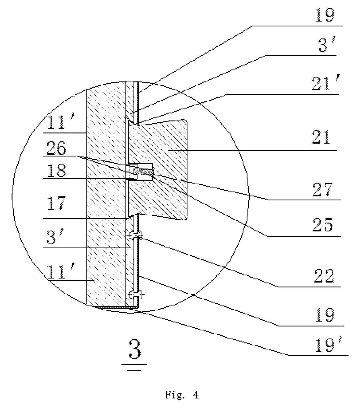
[0035]As shown in FIGS. 2, 3, and 4, the main body 1 of a device of the invention includes an inner chamber 2, an outer wall body 3, a small outer wall 3′, and a double valve 4. The inner chamber 2 may be a rectangular body with a hollow cavity, having the following dimensions: the long side 12′ has an inner dimension of 300-1100 mm and an outside dimension of 400-1200 mm; the short side 11 and 11′ have an inner dimension of 200-1000 mm and an outer dimension of 300-1100 mm. Along the short side 11′ of the inner chamber 2 there is a dovetail-shaped t...
example 2
[0039]As shown in FIG. 8, on one side of the joint 8, there is a sealing trough (groove) 8′ to facilitate tight-seal installation to prevent leakage.
[0040]As shown in FIG. 1, the bottom section of the main body 1 with a double valve 4 is referred to as a base section 10. The lengths of the base section 10 is ≤50 m. The bottom section of the main body 1 without a double valve 4 is referred to as an auxiliary section 10′. The lengths of the auxiliary sections 10′ range between 1500 mm and 15000 mm. The lengths of the short sides 11, 11′ of the main body 1 correspond to the thickness of the underground continuous wall and are designed to meet the protection structure strength and waterproof requirements. Their lengths may be in the range from 300 mm to 1300 mm.
example 3
[0041]As shown in FIG. 1, FIG. 6, FIG. 7, and FIG. 9, the front side view of the double valve 4 is a triangle, with a valve side panel 4′ that has a vertical side aligned with the inner cavity 2 vertical sidewall and a blade-shaped (sharpened on one side) top. Along the center of the long sides 12′ of the inner cavity 2, the double valve is divided into two valves. As shown in FIG. 6 and FIG. 9, each valve has at least two shaft pin holes at the joint with the short sides 11, 11′ of the inner chamber 2. The bottom of the short sides 11, 11′ of the inner chamber 2 also has at least two shaft pinholes 13′ offset from the pinholes 13 such that they can forma concentric shaft hole, through which a shaft pin 14 is inserted to achieve hinged connection. As shown in FIG. 12 and FIG. 13, the double valve 4 can also adopt other shapes, such as a plate valve 16. The valve plate valve 16 is formed with two pieces of a certain thickness of flat plate that close and meet at the center of the lon...
PUM
 Abstract
Description
Claims
Application Information
 - R&D
- Intellectual Property
- Life Sciences
- Materials
- Tech Scout
- Unparalleled Data Quality
- Higher Quality Content
- 60% Fewer Hallucinations
Browse by: Latest US Patents, China's latest patents, Technical Efficacy Thesaurus, Application Domain, Technology Topic, Popular Technical Reports.
© 2025 PatSnap. All rights reserved.Legal|Privacy policy|Modern Slavery Act Transparency Statement|Sitemap|About US| Contact US: help@patsnap.com


