
Light splitting apparatus utilizing glass substrate for phase retardation

a technology of phase retardation and light splitting, which is applied in the direction of optics, polarising elements, instruments, etc., can solve the problems of difficult to achieve precision alignment between the phase retarder and the polarizer, and the total thickness of the stacking chips is reduced. , the effect of enhancing product reliability

Active Publication Date: 2019-09-10
HIMAX TECH LTD
View PDF7 Cites 0 Cited by
  • Summary
  • Abstract
  • Description
  • Claims
  • Application Information

AI Technical Summary

Benefits of technology

[0005]The proposed light splitting apparatus may include a glass substrate used for light polarization and phase retardation (e.g. a glass substrate having a birefringence characteristic) to split light into different color light beams without the use of a phase retarder, thus reducing manufacturing costs, enhancing product reliability and decreasing the total thickness of the chips stacked in the proposed light splitting apparatus. Additionally, as the proposed light splitting apparatus may utilize optical adhesives to bond different glass substrates together, the black coating may be applied only once to prevent edge leakage of light.

Problems solved by technology

However, optical performance of a phase retarder degrades in short wavelength applications because the phase retarder is made of plastic materials.
In addition, the phase retarder will exhibit undesirable wrinkles when attached to a polarizer, and precision alignment between the phase retarder and the polarizer is difficult to achieve.
Further, the conventional apparatus utilizes pressure-sensitive adhesives to bond chips each including polarizer(s) and phase retarder(s), but the chips cannot be bonded tightly in order to prevent damages to a microstructure on a phase retarder.
The bonded chips will exhibit low reliability and have a great thickness.

Method used


Image

  • Light splitting apparatus utilizing glass substrate for phase retardation
  • Light splitting apparatus utilizing glass substrate for phase retardation
  • Light splitting apparatus utilizing glass substrate for phase retardation

Examples


Embodiment Construction

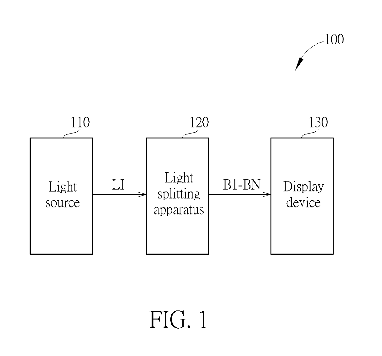
[0012]Please refer to FIG. 1, which is a block diagram illustrating an exemplary display apparatus according to an embodiment of the present invention. The display apparatus 100 may be implemented in a variety of forms, such as a television, a projection display apparatus, a portable display apparatus or a wearable display apparatus, and may include, but is not limited to a light source 110, a light splitting apparatus 120 and a display device. The light source 110 may emit incident light LI to the light splitting apparatus 120, and the light splitting apparatus 120 may utilize a plurality of glass substrates (or cover lens; not shown in FIG. 1) to split the incident light LI into a plurality of color light beams B1-BN (N is a positive integer greater than one), wherein at least one of the glass substrates is capable of polarizing light and retarding a phase of a light beam. Next, the display device 130 may display an image according to the color light beams B1-BN. By way of example...


PUM


Abstract

A light splitting apparatus includes a first glass substrate, a second glass substrate and a third glass substrate. The first glass substrate guides a first color light beam of incident light to a display device, and changes a polarization direction of a first intermediate light beam of the incident light to produce a second intermediate light beam. The first color light beam is polarized a first polarization direction. The second intermediate light beam includes a second color light beam polarized in a second polarization direction and a third color light beam. The second glass substrate guides the second color light beam polarized in the second polarization direction to the display device, and changes a polarization direction of the third color beam to a third polarization direction. The third glass substrate guides the third color light beam polarized in the third polarization direction to the display device.

Description

BACKGROUND OF THE INVENTION1. Field of the Invention[0001]The disclosed embodiments of the present invention relate to light splitting, and more particularly, to a light splitting apparatus including a glass substrate capable of polarizing light and retarding a phase of a light beam.2. Description of the Prior Art[0002]A conventional display apparatus utilizes polarizers, phase retarders and electrochromic substrates to control optical transmission paths of light beams therewithin. However, optical performance of a phase retarder degrades in short wavelength applications because the phase retarder is made of plastic materials. In addition, the phase retarder will exhibit undesirable wrinkles when attached to a polarizer, and precision alignment between the phase retarder and the polarizer is difficult to achieve. Further, the conventional apparatus utilizes pressure-sensitive adhesives to bond chips each including polarizer(s) and phase retarder(s), but the chips cannot be bonded ti...

Claims


Application Information

Patent Timeline
Patent Type & Authority Patents(United States)
IPC IPC(8): G02B27/28G02B5/30F21V8/00
CPCG02B27/286G02B6/0056G02B27/283G02B6/0065G02B5/3083G02B27/1006
Inventor CHUNG, JUN-WEN
Owner HIMAX TECH LTD
Features
  • Generate Ideas
  • Intellectual Property
  • Life Sciences
  • Materials
  • Tech Scout
  • Unparalleled Data Quality
  • Higher Quality Content
  • 60% Fewer Hallucinations
Learn More