
Electromagnetic flowmeter with adjustable electrode structures

a flowmeter and electrode structure technology, applied in the field of electromagnetic flowmeters, can solve problems such as failures or inaccuracy in measurement of electromagnetic flowmeters, noise of electronic signals, and damage to detecting portions of electrode structures, and achieve the effect of enhancing flexibility and increasing service life of electromagnetic flowmeters

Active Publication Date: 2019-09-17
FINETEK CO LTD
View PDF11 Cites 1 Cited by
  • Summary
  • Abstract
  • Description
  • Claims
  • Application Information

AI Technical Summary

Benefits of technology

[0007]Accordingly, an object of the present invention is to provide an electromagnetic flowmeter with adjustable electrode structures for compensating the wear of the electrode structures and adjusting the relative position of electrode structures; therefore, the flow field can be perpendicular to and orthogonal to the flow direction so as to maintain correct measurement results and reduce noises of the electronic signal so that the maintenance time can be shorten and the process will be simplified to maintain the capacity and increase the service life of the electromagnetic flowmeter.
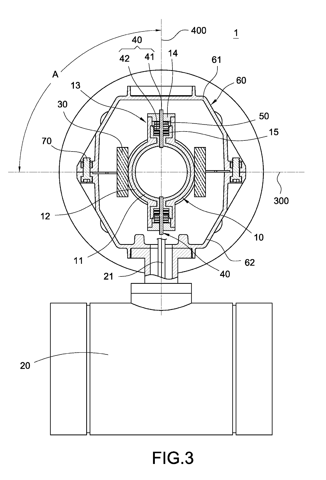
[0009]Comparing to the prior art, the actuator element of the present invention is electrically connected with the control module and electrode structures. The actuator element is driven by an external force to take one of the electrode structures toward the mounting tube liner 11 inside and being orthogonal to a shaft of the mounting tube liner for compensating the wear of the electrode structure so as to obtain a correct measurement result and increase service life. Furthermore, the position of the electrode structure on the measurement tube can be adjusted depends on actual situations; thus the flexibility of the electromagnetic flowmeter will be enhanced.

Problems solved by technology

However, fluid in the tube might cause damages to detecting portions of the electrode structures.
Therefore, failures or inaccuracies of measurement of the electromagnetic flowmeter might be occurred after using a considerable amount of time so that noises of the electronic signal are generated.
In addition, metal shells of traditional electromagnetic flowmeter are mostly sealed by welding to avoid moisture penetration for ensuring normal operations of internal electrode structures and coils, but this welding process causes difficulty in replacing the electrode structures inside the metal shell.
As a result, pipeline-related devices must be shut down to replace the electromagnetic flowmeter that results in disruptions of production, a lower capacity, and a high cost.

Method used


Image

  • Electromagnetic flowmeter with adjustable electrode structures
  • Electromagnetic flowmeter with adjustable electrode structures
  • Electromagnetic flowmeter with adjustable electrode structures

Examples


Embodiment Construction

[0017]In cooperation with attached drawings, the technical contents and detailed description of the invention are described thereinafter according to a number of preferable embodiments, being not used to limit its executing scope. Any equivalent variation and modification made according to appended claims is all covered by the claims claimed by the present invention.

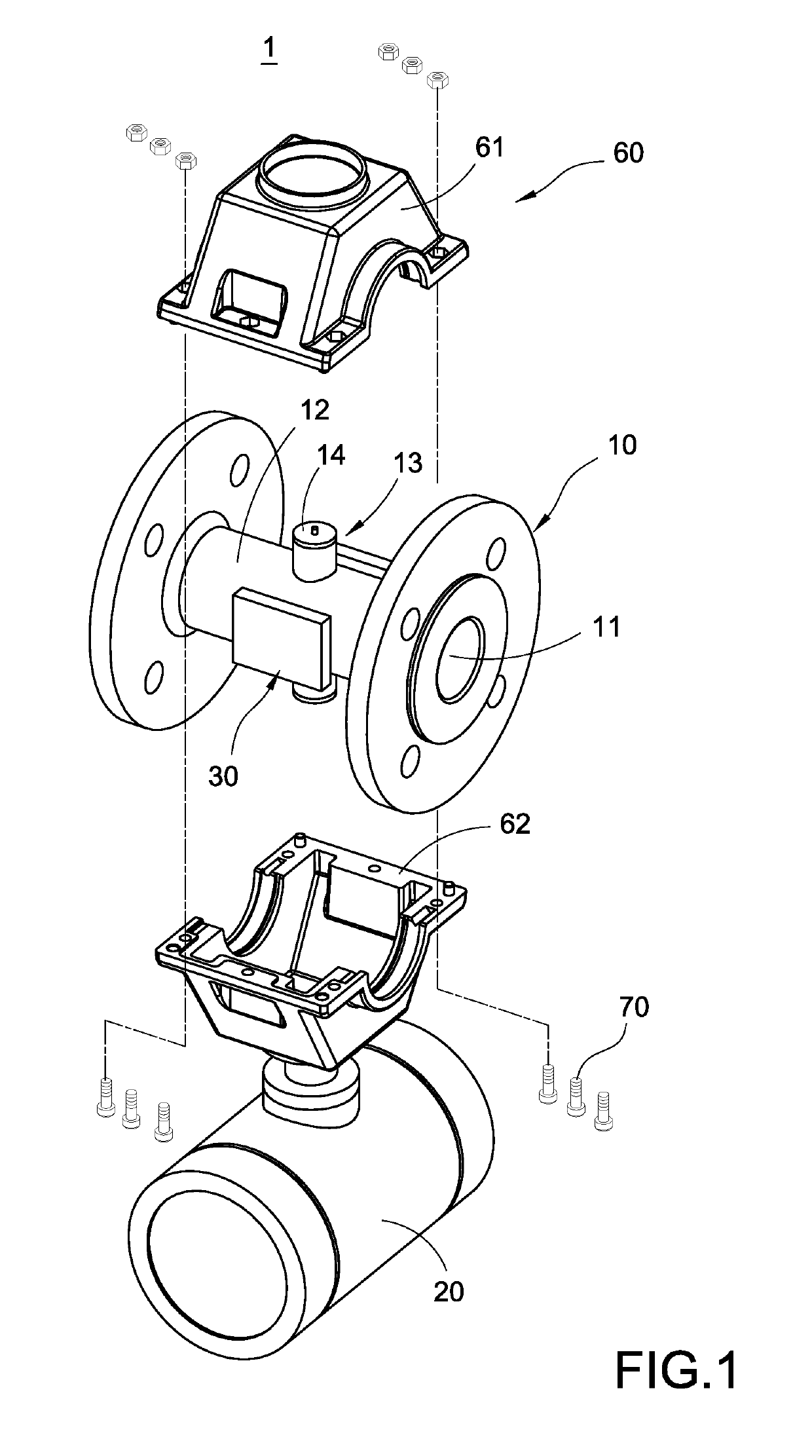
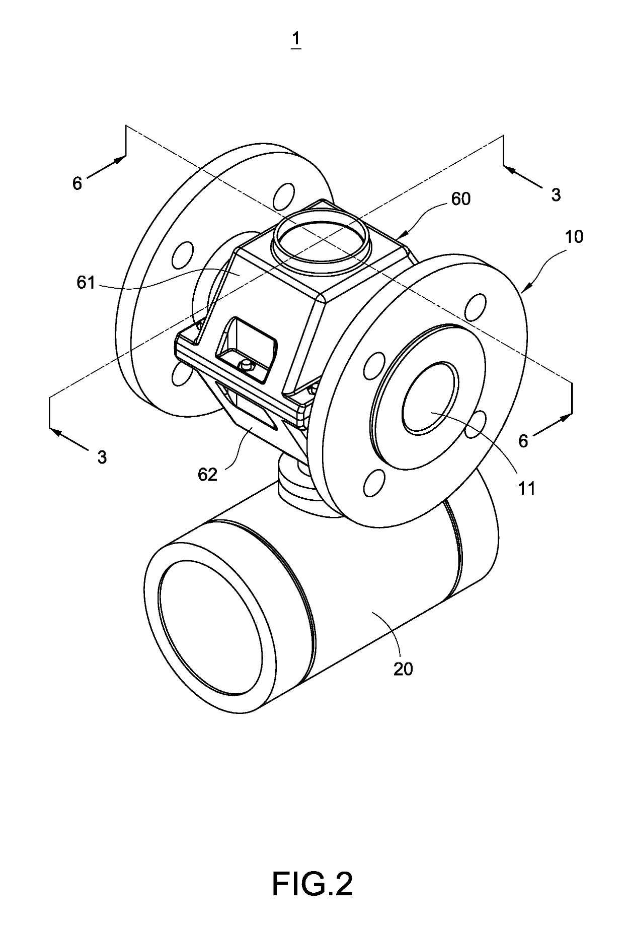
[0018]Please refer to FIG. 1 to FIG. 3, which depict a perspective explosion schematic view, a perspective schematic view and a cross sectional view of one side of the electromagnetic flowmeter with adjustable electrode structures. The electromagnetic flowmeter 1 with adjustable electrode structures includes a measurement tube 10, a control module 20, a magnetic field module 30, an electrode structure 40 and at least one actuator element 50. The magnetic field module 30 and the electrode structure 40 are fixed on two opposite sides of the measurement tube 10 separately. Moreover, the control module 20 controls the magnet...


PUM


Abstract

An electromagnetic flowmeter includes a measurement tube having a mounting tube liner and a control module installed in an outer side of the measurement tube. A magnetic field module is installed in an outer side being orthogonal to a shaft of the measurement tube without contacting the working fluid. An electrode structure is disposed on an outer surface of the measurement tube and partially extended in the mounting tube liner to contact the working fluid. The actuator element is electrically connected with the control module and connected with the electrode structure. The actuator element is driven by an external force to drive the electrode structure toward the mounting tube liner inside and being orthogonal to the mounting tube liner for compensating the wear of the electrode structure so as to obtain a correct measurement result and increase the service life.

Description

BACKGROUND OF THE INVENTION[0001]Field of the Invention[0002]The present invention generally relates to an electromagnetic flowmeter and, in particular to an electromagnetic flowmeter with adjustable electrode structures.[0003]Description of Prior Art[0004]An electromagnetic flowmeter usually measures a flow rate of a conductive fluid (such as water, etc.) by use of electromagnetic induction. The electromagnetic flowmeter is mainly composed of a measurement tube, a pair of electrode structures arranged on the measurement tube and a pair of coils. Additionally, a magnetic field is formed in the measurement tube and an electromotive force is generated between the electrode structures after the coils are energized. Therefore, the electromotive force of the magnetic field is changed when the fluid passes through the measurement body, and then the flow rate of the fluid can be calculated.[0005]An electromagnetic flowmeter usually detects the fluid in the tube through the electrode struct...

Claims


Application Information

Patent Timeline
Patent Type & Authority Patents(United States)
IPC IPC(8): G01F1/58
CPCG01F1/584G01F1/588
Inventor HUANG, CHIEN-LUNGCHEN, SHENG-SHOUHOU, YI-LIANGCHEN, CHUN-JU
Owner FINETEK CO LTD
Learn More