Electric connector with contact members having different thickness

a technology of contact members and contact members, which is applied in the direction of solder/welded conductive connections, coupling device connections, electrical apparatuses, etc., can solve the problems of increasing the number of contact members, lengthening or heightening, and reducing the conductor resistance of the thickness-increased contact members. , the effect of increasing the size of the electric connector

Active Publication Date: 2019-09-17
DAIICHI SEIKO CO LTD
View PDF17 Cites 3 Cited by
  • Summary
  • Abstract
  • Description
  • Claims
  • Application Information

AI Technical Summary

Benefits of technology

[0021]As described above, in the electric connector according to the present invention, one or more of the plurality of contact members are formed thicker than the rest of the contact members, and thus the conductor resistance of the thickness-increased contact members is reduced in accordance with an increment in thickness. As a result, the number of the contact members does not have to be increased even in a case where the supply electric power with respect to the electric connector is relatively large, and an increase in the size of the electric connector such as lengthening and heightening can be suppressed. In addition, the electric connector according to the present invention is configured such that the contact pressure of the contact members with respect to the flat plate-shaped signal transmission medium is increased and the retention of the flat plate-shaped signal transmission medium is enhanced by the thickness-increased contact members being pressure-welded to the flat plate-shaped signal transmission medium inserted into the insulating housing, and thus lengthening and heightening of the electric connector can be easily avoided with a simple configuration even in a case where the supply electric power is relatively large. As a result, the reliability of the electric connector can be enhanced to a significant extent and in an inexpensive manner.

Problems solved by technology

As a matter of course, however, the adoption of a configuration in which a plurality of contact members is used for the transmission of a single signal causes the number of the contact members to increase, and then a problem arises in the form of the lengthening or heightening of an electric connector as a whole.

Method used


Image

  • Electric connector with contact members having different thickness
  • Electric connector with contact members having different thickness
  • Electric connector with contact members having different thickness

Examples


Embodiment Construction

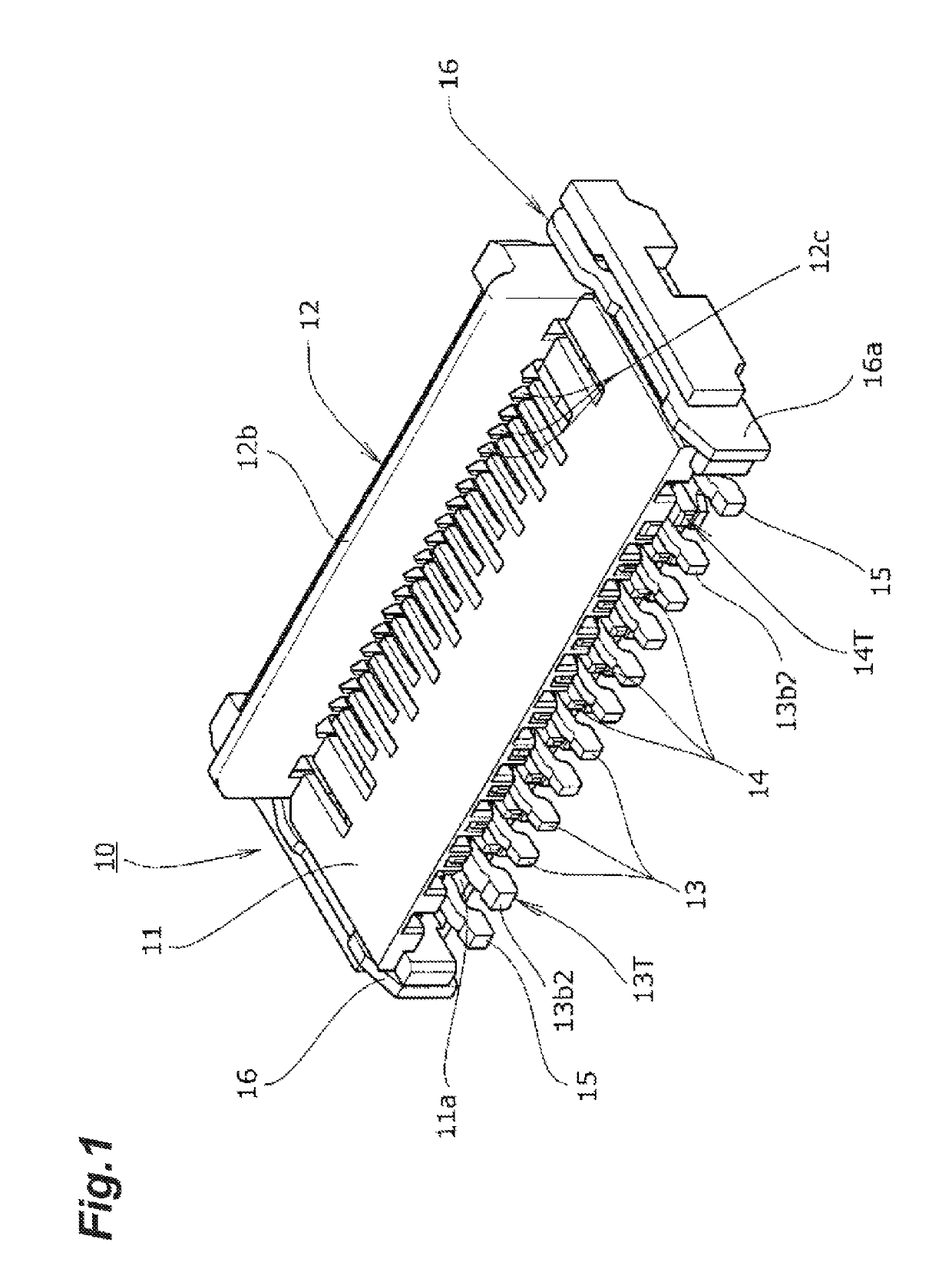
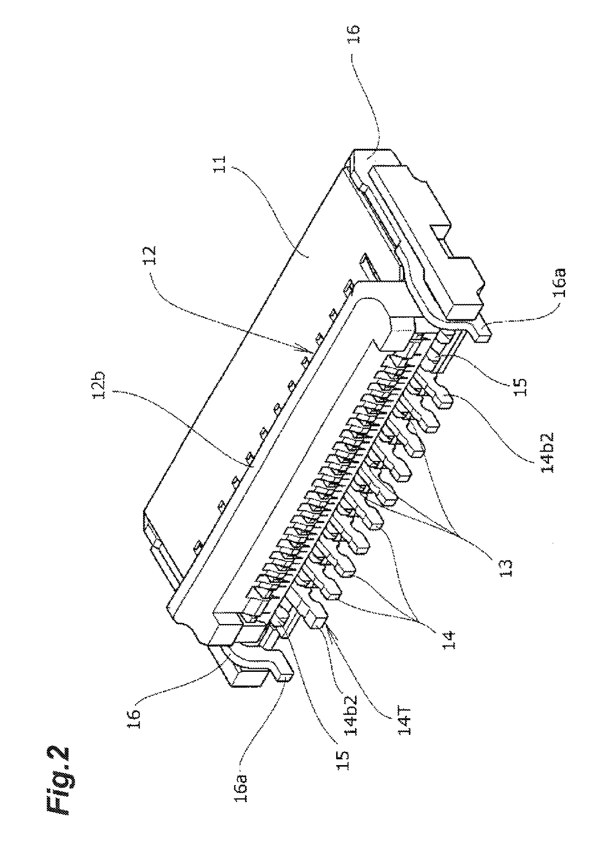
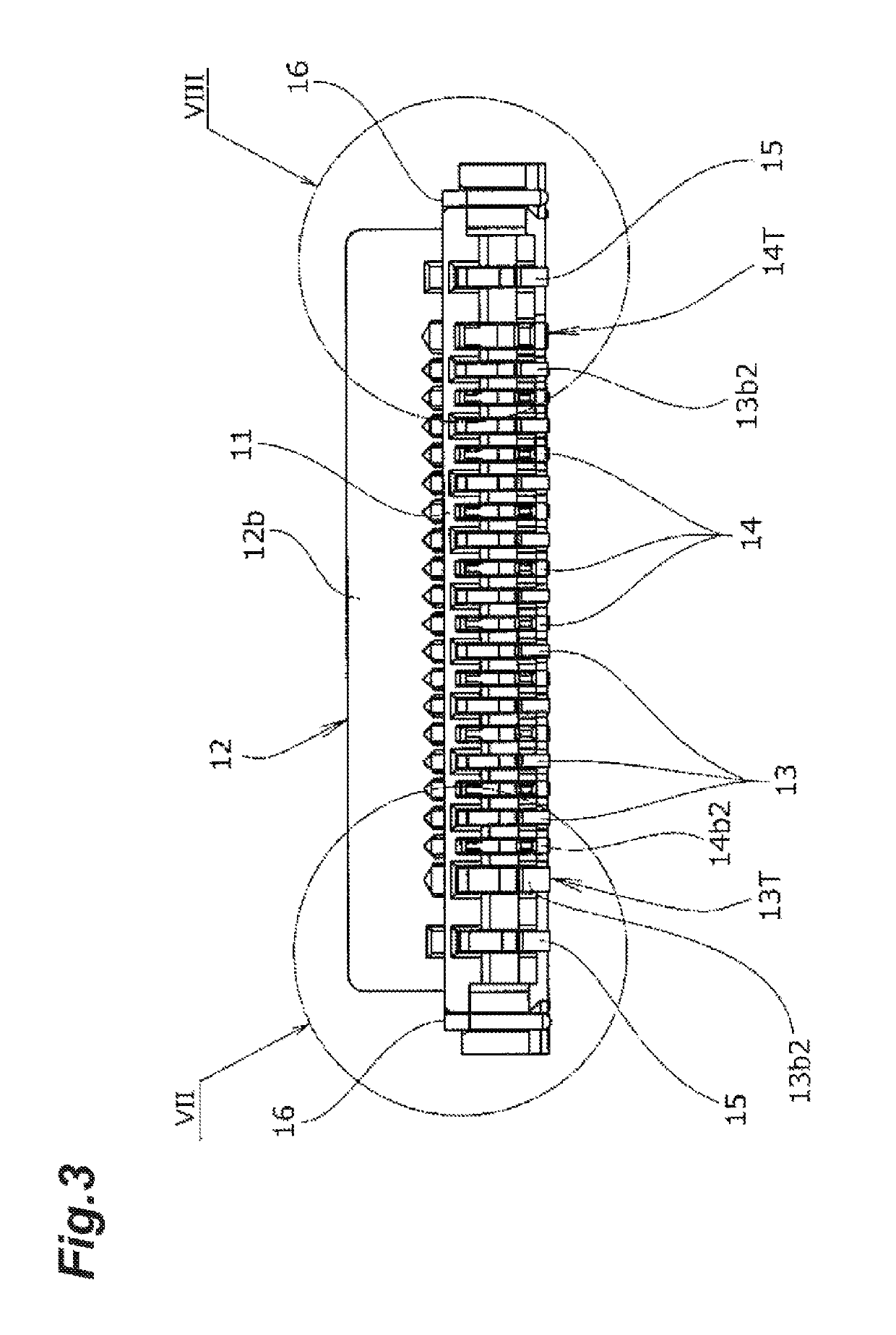
[0042]Hereinafter, an embodiment in which the present invention is applied to an electric connector mounted and used on a surface of a printed wiring substrate so that connection of a flat plate-shaped signal transmission medium including a flexible printed circuit (FPC), a flexible flat cable (FFC), and so on is performed will be described in detail based on the drawings.

[0043]An electric connector 10 illustrated in FIGS. 1 to 8 is an electric connector including a so-called back flip-type structure and provided with an actuator 12 as connection operation means on the rear end edge side of an insulating housing 11 (right end edge side in FIGS. 5 and 6), and the actuator 12 described above is configured to be rotated to be pushed down toward the rear side (right side in FIGS. 5 and 6) that is on the side opposite to the connector front end side (left end side in FIGS. 5 and 6) on which a terminal part of a flat plate-shaped signal transmission medium (FPC, FFC, or the like) F is ins...


PUM


Abstract

To be capable of easily avoiding lengthening and heightening with a simple configuration even in a case where relatively large electric power is supplied.Provided is a configuration in which the conductor resistance of a plurality of contact members 13 and 14 is reduced in accordance with an increment in thickness and energization allowable electric power is increased by one of more of the contact members 13 and 14 being formed thicker than the rest so that an increase in the size of an electric connector such as lengthening and heightening is prevented even in a case where the supply electric power with respect to the electric connector is large and the retention of a flat plate-shaped signal transmission medium F is enhanced by contact portions of the thickness-increased contact members 13 and 14 being pressure-welded to the flat plate-shaped signal transmission medium F.

Description

CROSS-REFERENCE TO RELATED APPLICATIONS[0001]This application is a 35 U.S.C. § 371 national phase application of PCT / JP2016 / 066589, filed Jun. 3, 2016, which is based upon and claims the benefit of priority from Japanese Patent Application No. 2015-136599, filed Jul. 8, 2015.TECHNICAL FIELD[0002]The present invention relates to an electric connector configured such that clamping is performed by contact members being pressure-welded to both side surfaces of a flat plate-shaped signal transmission medium inserted into an insulating housing for sandwiching from both sides.BACKGROUND ART[0003]In general, various electric connectors are widely used in various types of electrical equipment, devices, and so on for electrical connection of a signal transmission medium having a flat plate shape (hereinafter, referred to as a flat plate-shaped signal transmission medium) such as a flexible printed circuit (FPC) and a flexible flat cable (FFC). For example, in an electric connector that is mou...

Claims


Application Information

Patent Timeline
Patent Type & Authority Patents(United States)
IPC IPC(8): H01R12/72H01R12/79H01R12/57H01R12/70H01R12/88H01R4/02H01R12/71H01R12/77
CPCH01R12/79H01R12/721H01R12/7011H01R12/57H01R12/88H01R12/774H01R12/707H01R4/028H01R12/716H01R12/72
Inventor ISHIMARU, MASAO
Owner DAIICHI SEIKO CO LTD
Why Eureka
Try Eureka