Satellite comprising an optical photography instrument

a technology of optical photography and satellites, applied in the field of space vehicles, can solve the problems of limited space available for satellites, limited resolution, and impaired performance of instruments, and achieve the effect of improving performan

Active Publication Date: 2019-10-15
AIRBUS DEFENCE & SPACE
View PDF24 Cites 3 Cited by
  • Summary
  • Abstract
  • Description
  • Claims
  • Application Information

AI Technical Summary

Benefits of technology

[0017]One object of the present invention is therefore to propose a new satellite comprising...

Problems solved by technology

However, the transmission of stresses to the satellite must be controlled carefully, particularly if the satellite has a delicate optical instrument that impacts and vibrations can misalign or damage.
The integrity of the instrument and the alignment of its components may be affected by impacts and vibrations during launch and release, p...

Method used


Image

  • Satellite comprising an optical photography instrument
  • Satellite comprising an optical photography instrument
  • Satellite comprising an optical photography instrument

Examples


Embodiment Construction

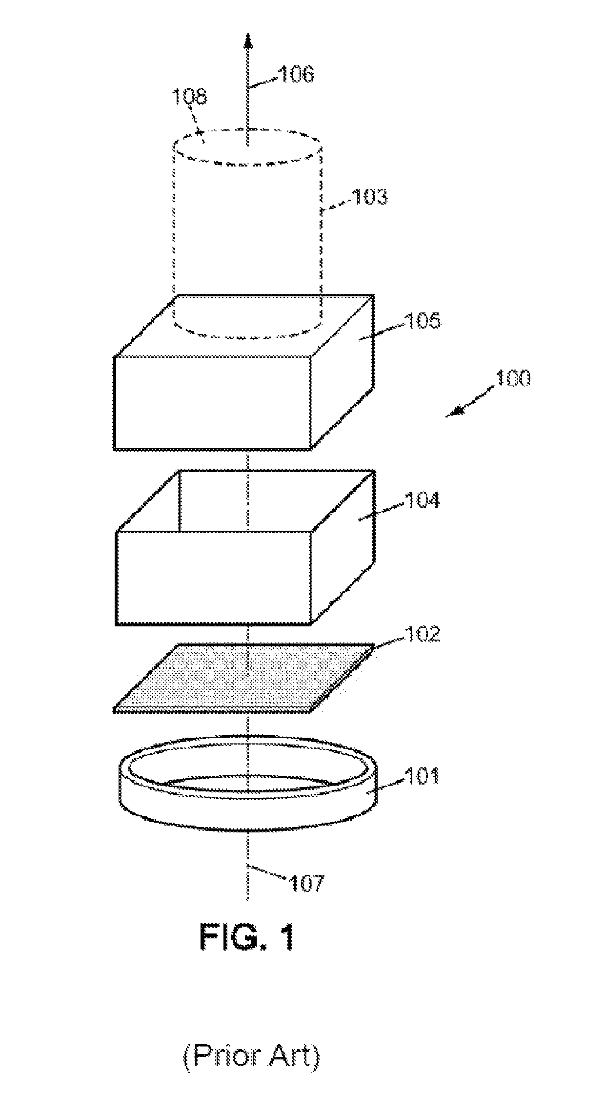
[0040]FIG. 1 has already been described in the introduction.

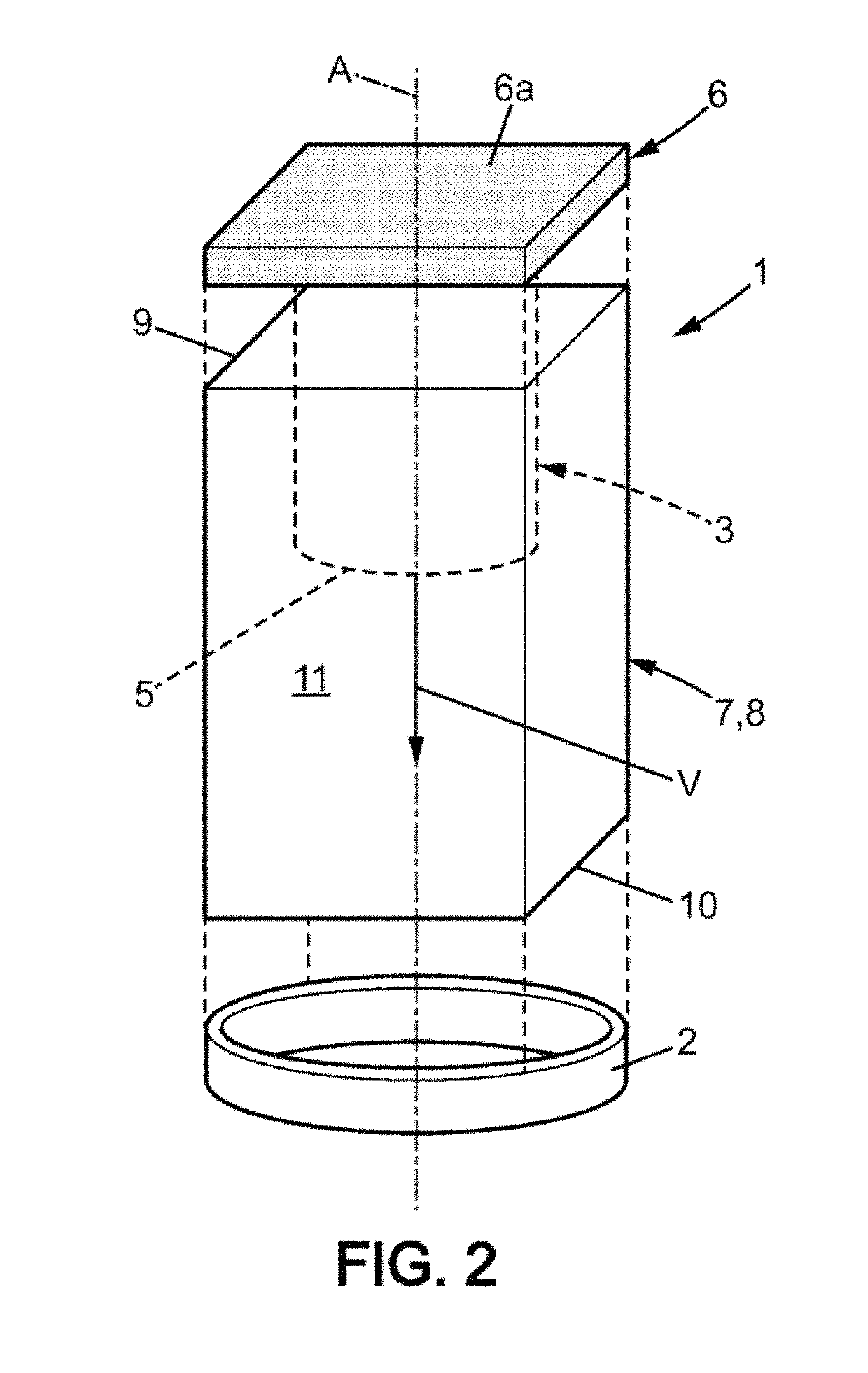
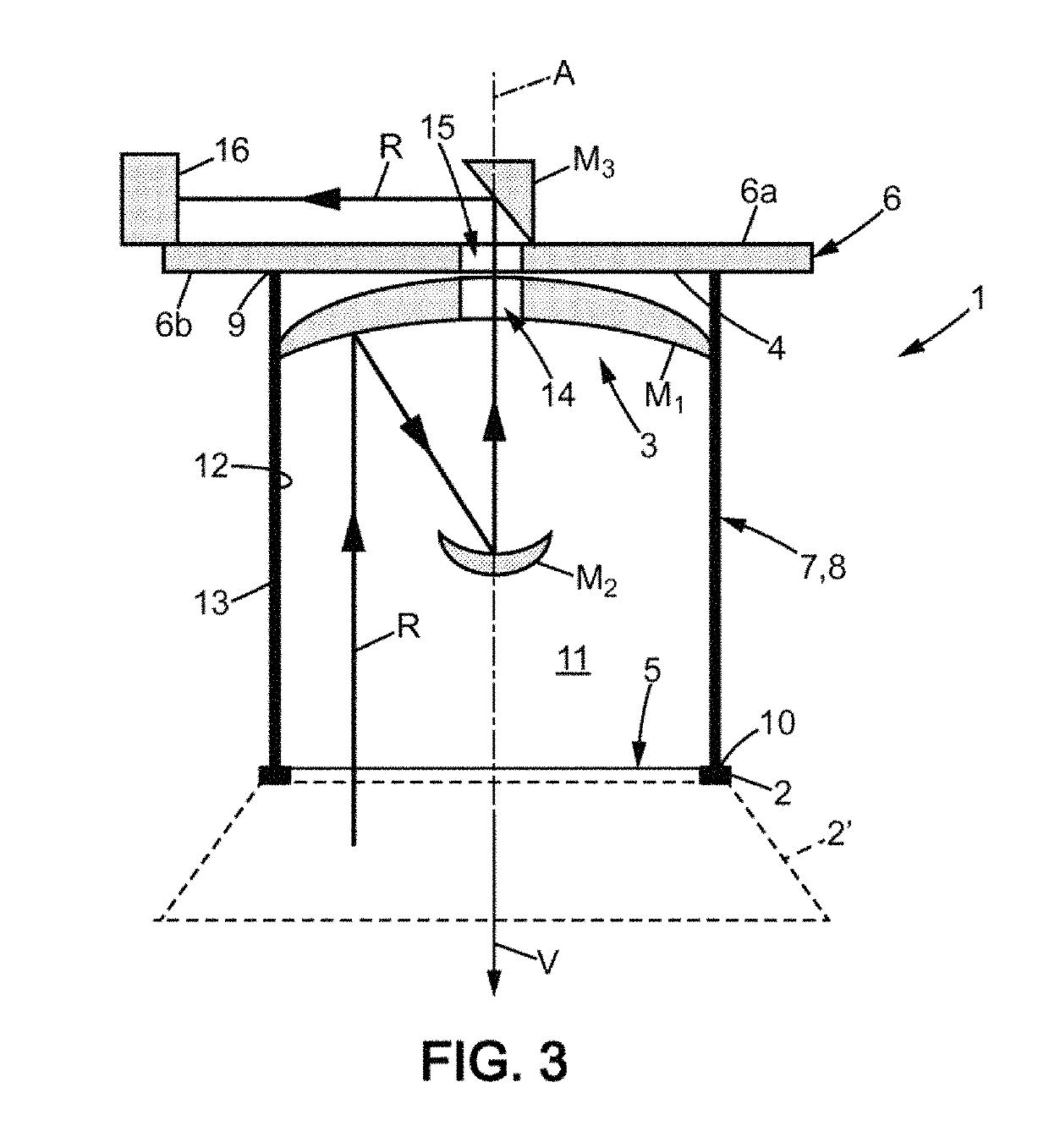
[0041]In FIGS. 2 and 3, a first embodiment of a satellite 1 according to the invention is schematically represented, comprising a launch vehicle interface system 2 intended to be removably secured to a satellite interface system 2′ of a satellite launch vehicle represented in dashed lines in FIG. 3. The interface system 2 is usually an interface ring of axis A, as will be the case in the following description. The diameter of the interface ring 2 is generally selected from standard spatial dimensions, which are: 937 mm, 1194 mm, and 1666 mm. The satellite interface system 2′ is then annular and of complementary dimensions. The two rings 2, 2′ are assembled using a locking mechanism, not shown here, which is for example in the form of a clamping belt, also called a band, which is integral to one of the two rings, preferably the launch vehicle interface ring 2 of the satellite 1.

[0042]The satellite 1 comprises an optical inst...


PUM


Abstract

A satellite includes: at least one optical photography instrument including a main lens having an optical axis and the optical instrument having a field of view; at least one launcher interface system, intended for being removably secured to a satellite interface system of a launcher of the satellite; a linking device between the launcher interface and the optical instrument extending substantially parallel to the optical axis of the main lens between an upper end and a lower end; the launcher interface system is connected to the linking device by the lower end and the optical axis of the optical instrument is directed from the upper end towards the lower end of the linking device, the launcher interface system being outside the field of view of the instrument.

Description

BACKGROUND OF THE INVENTIONField of the Invention[0001]The invention relates to the field of space vehicles, specifically satellites whose mission involves the presence of optical instruments, such as satellites for observation or measurement.Description of the Related Art[0002]In order to be released in space, the satellite is first mounted and fixed on a launch vehicle. The launch vehicle is then propelled into space, and then the satellite is separated from the launch vehicle for release in its determined orbit.[0003]Before being released, as well as during the release phase, the satellite on the launch vehicle is subjected to many stresses related to impacts and vibrations, and the attachment of the satellite to the launch vehicle as well as the satellite itself must be able to withstand them. However, the transmission of stresses to the satellite must be controlled carefully, particularly if the satellite has a delicate optical instrument that impacts and vibrations can misalig...

Claims


Application Information

Patent Timeline
IPC IPC(8): G02B23/00B64G1/10G02B23/02B64G1/64G02B23/16B64G1/40
CPCB64G1/405B64G1/10B64G1/641B64G1/1021B64G1/402B64G1/1028G02B23/02G03B15/006G02B23/16
Inventor FAYE, FRÉDÉRICBEAUFUME, ERICCOTTIER, JACQUES
Owner AIRBUS DEFENCE & SPACE
Why Eureka
Try Eureka